参数资料
| 型号: | ISL6441IR-TK |
| 厂商: | Intersil |
| 文件页数: | 15/18页 |
| 文件大小: | 0K |
| 描述: | IC CTRLR PWM DUAL 1.4MHZ 28-QFN |
| 标准包装: | 1,000 |
| 应用: | 电源 |
| 电流 - 电源: | 2mA |
| 电源电压: | 5.6 V ~ 24 V |
| 工作温度: | -40°C ~ 85°C |
| 安装类型: | 表面贴装 |
| 封装/外壳: | 28-VFQFN 裸露焊盘 |
| 供应商设备封装: | 28-QFN 裸露焊盘(5x5) |
| 包装: | 带卷 (TR) |
�� �
�
�ISL6441�
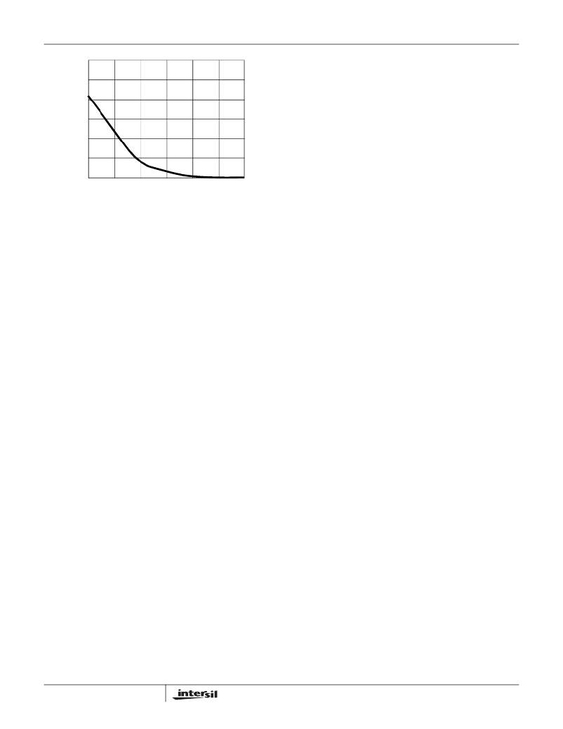
�60�
�50�
�40�
�30�
�20�
�10�
�Layout� Considerations�
�1.� The� Input� capacitors,� Upper� FET,� Lower� FET,� Inductor�
�and� Output� capacitor,� should� be� placed� first.� Isolate� these�
�power� components� on� the� topside� of� the� board� with� their�
�ground� terminals� adjacent� to� one� another.� Place� the� input�
�high� frequency� decoupling� ceramic� capacitor� very� close�
�to� the� MOSFETs.�
�2.� Use� separate� ground� planes� for� power� ground� and� small�
�signal� ground.� Connect� the� SGND� and� PGND� together�
�close� of� the� IC.� Do� not� connect� them� together� anywhere�
�else.�
�0�
�0.79�
�0.80�
�0.81� 0.82� 0.83�
�FEEDBACK� VOLTAGE� (V)�
�0.84�
�0.85�
�3.� The� loop� formed� by� Input� capacitor,� the� top� FET� and� the�
�bottom� FET� must� be� kept� as� small� as� possible.�
�FIGURE� 21.� LINEAR� CONTROLLER� GAIN�
�Base-Drive� Noise� Reduction�
�The� high-impedance� base� driver� is� susceptible� to� system�
�noise,� especially� when� the� linear� regulator� is� lightly� loaded.�
�Capacitively� coupled� switching� noise� or� inductively� coupled�
�EMI� onto� the� base� drive� causes� fluctuations� in� the� base�
�current,� which� appear� as� noise� on� the� linear� regulator� ’s�
�output.� Keep� the� base� drive� traces� away� from� the� step-down�
�converter,� and� as� short� as� possible,� to� minimize� noise�
�coupling.� A� resistor� in� series� with� the� gate� drivers� reduces�
�the� switching� noise� generated� by� PWM.� Additionally,� a�
�bypass� capacitor� may� be� placed� across� the� base-to-emitter�
�resistor.� This� bypass� capacitor,� in� addition� to� the� transistor� ’s�
�input� capacitor,� could� bring� in� second� pole� that� will�
�destabilize� the� linear� regulator.� Therefore,� the� stability�
�requirements� determine� the� maximum� base-to-emitter�
�capacitance.�
�Layout� Guidelines�
�Careful� attention� to� layout� requirements� is� necessary� for�
�successful� implementation� of� an� ISL6441� based� DC/DC�
�converter.� The� ISL6441� switches� at� a� very� high� frequency�
�and� therefore� the� switching� times� are� very� short.� At� these�
�switching� frequencies,� even� the� shortest� trace� has�
�significant� impedance.� Also� the� peak� gate� drive� current� rises�
�significantly� in� extremely� short� time.� Transition� speed� of� the�
�current� from� one� device� to� another� causes� voltage� spikes�
�across� the� interconnecting� impedances� and� parasitic� circuit�
�elements.� These� voltage� spikes� can� degrade� efficiency,�
�generate� EMI,� increase� device� over� voltage� stress� and�
�ringing.� Careful� component� selection� and� proper� PC� board�
�layout� minimizes� the� magnitude� of� these� voltage� spikes.�
�There� are� two� sets� of� critical� components� in� a� DC/DC�
�converter� using� the� ISL6441;� the� switching� power�
�components� and� the� small� signal� components.� The�
�switching� power� components� are� the� most� critical� from� a�
�layout� point� of� view� because� they� switch� a� large� amount� of�
�energy� so� they� tend� to� generate� a� large� amount� of� noise.�
�The� critical� small� signal� components� are� those� connected� to�
�sensitive� nodes� or� those� supplying� critical� bias� currents.� A�
�multi-layer� printed� circuit� board� is� recommended.�
�15�
�4.� Insure� the� current� paths� from� the� input� capacitor� to� the�
�MOSFET;� to� the� output� inductor� and� output� capacitor� are�
�as� short� as� possible� with� maximum� allowable� trace�
�widths.�
�5.� Place� The� PWM� controller� IC� close� to� lower� FET.� The�
�LGATE� connection� should� be� short� and� wide.� The� IC� can�
�be� best� placed� over� a� quiet� ground� area.� Avoid� switching�
�ground� loop� current� in� this� area.�
�6.� Place� VCC_5V� bypass� capacitor� very� close� to� VCC_5V�
�pin� of� the� IC� and� connect� its� ground� to� the� PGND� plane.�
�7.� Place� the� gate� drive� components� BOOT� diode� and� BOOT�
�capacitors� together� near� controller� IC.�
�8.� The� output� capacitors� should� be� placed� as� close� to� the�
�load� as� possible.� Use� short� wide� copper� regions� to�
�connect� output� capacitors� to� load� to� avoid� inductance� and�
�resistances.�
�9.� Use� copper� filled� polygons� or� wide� but� short� trace� to�
�connect� junction� of� upper� FET,� lower� FET� and� output�
�inductor.� Also� keep� the� PHASE� node� connection� to� the� IC�
�short.� Do� not� unnecessarily� oversize� the� copper� islands�
�for� PHASE� node.� Since� the� phase� nodes� are� subjected� to�
�very� high� dv/dt� voltages,� the� stray� capacitor� formed�
�between� these� islands� and� the� surrounding� circuitry� will�
�tend� to� couple� switching� noise.�
�10.� Route� all� high� speed� switching� nodes� away� from� the�
�control� circuitry.�
�11.� Create� a� separate� small� analog� ground� plane� near� the� IC.�
�Connect� SGND� pin� to� this� plane.� All� small� signal�
�grounding� paths� including� feedback� resistors,� current�
�limit� setting� resistors� and� SYNC/SDx� pull-down� resistors�
�should� be� connected� to� this� SGND� plane.�
�12.� Ensure� the� feedback� connection� to� output� capacitor� is�
�short� and� direct.�
�Component� Selection� Guidelines�
�MOSFET� Considerations�
�The� logic� level� MOSFETs� are� chosen� for� optimum� efficiency�
�given� the� potentially� wide� input� voltage� range� and� output�
�power� requirements.� Two� N-Channel� MOSFETs� are� used� in�
�each� of� the� synchronous-rectified� buck� converters� for� the�
�PWM1� and� PWM2� outputs.� These� MOSFETs� should� be�
�selected� based� upon� r� DS(ON)� ,� gate� supply� requirements,�
�and� thermal� management� considerations.�
�FN9197.3�
�May� 26,� 2009�
�相关PDF资料 |
PDF描述 |
|---|---|
| ISL6443AIVZ | IC CTRLR SGL/STP DWN PWM 28TSSOP |
| ISL6443IR-TK | IC CTRLR PWM DUAL 300KHZ 28-QFN |
| ISL6444CA-T | IC CONTROLLER DDR 28-QSOP |
| ISL6445IAZ | IC REG CTRLR BUCK PWM CM 24-QSOP |
| ISL6455AIRZS2698 | IC REG TRPL SYNC DUAL LDO 24-QFN |
相关代理商/技术参数 |
参数描述 |
|---|---|
| ISL6441IRZ | 功能描述:IC CTRLR SGL/STEP DOWN PWM 28QFN RoHS:是 类别:集成电路 (IC) >> PMIC - 电源管理 - 专用 系列:- 产品培训模块:Lead (SnPb) Finish for COTS Obsolescence Mitigation Program 标准包装:50 系列:- 应用:热电冷却器 电流 - 电源:- 电源电压:3 V ~ 5.5 V 工作温度:-40°C ~ 85°C 安装类型:表面贴装 封装/外壳:28-SOIC(0.173",4.40mm 宽)裸露焊盘 供应商设备封装:28-TSSOP 裸露焊盘 包装:管件 产品目录页面:1410 (CN2011-ZH PDF) |
| ISL6441IRZS2695 | 制造商:Intersil Corporation 功能描述: |
| ISL6441IRZ-T | 功能描述:IC CTRLR PWM DUAL 1.4MHZ 28-QFN RoHS:是 类别:集成电路 (IC) >> PMIC - 电源管理 - 专用 系列:- 应用说明:Ultrasound Imaging Systems Application Note 产品培训模块:Lead (SnPb) Finish for COTS Obsolescence Mitigation Program 标准包装:37 系列:- 应用:医疗用超声波成像,声纳 电流 - 电源:- 电源电压:2.37 V ~ 6 V 工作温度:0°C ~ 70°C 安装类型:表面贴装 封装/外壳:56-WFQFN 裸露焊盘 供应商设备封装:56-TQFN-EP(8x8) 包装:管件 |
| ISL6441IRZ-TK | 功能描述:IC CTRLR PWM 1.4MHZ DUAL 28-QFN RoHS:是 类别:集成电路 (IC) >> PMIC - 电源管理 - 专用 系列:- 应用说明:Ultrasound Imaging Systems Application Note 产品培训模块:Lead (SnPb) Finish for COTS Obsolescence Mitigation Program 标准包装:37 系列:- 应用:医疗用超声波成像,声纳 电流 - 电源:- 电源电压:2.37 V ~ 6 V 工作温度:0°C ~ 70°C 安装类型:表面贴装 封装/外壳:56-WFQFN 裸露焊盘 供应商设备封装:56-TQFN-EP(8x8) 包装:管件 |
| ISL6442EVAL1Z | 功能描述:EVAL BOARD FOR ISL6442 RoHS:是 类别:编程器,开发系统 >> 评估板 - DC/DC 与 AC/DC(离线)SMPS 系列:- 产品培训模块:Obsolescence Mitigation Program 标准包装:1 系列:True Shutdown™ 主要目的:DC/DC,步升 输出及类型:1,非隔离 功率 - 输出:- 输出电压:- 电流 - 输出:1A 输入电压:2.5 V ~ 5.5 V 稳压器拓扑结构:升压 频率 - 开关:3MHz 板类型:完全填充 已供物品:板 已用 IC / 零件:MAX8969 |
发布紧急采购,3分钟左右您将得到回复。