- 您现在的位置:买卖IC网 > PDF目录17331 > ISL8107EVAL2Z (Intersil)EVAL BOARD 2 FOR ISL8107 PDF资料下载
参数资料
| 型号: | ISL8107EVAL2Z |
| 厂商: | Intersil |
| 文件页数: | 12/16页 |
| 文件大小: | 0K |
| 描述: | EVAL BOARD 2 FOR ISL8107 |
| 标准包装: | 1 |
| 系列: | * |
�� �
�
�ISL8107�
�current.� The� response� time� is� the� time� required� to� slew� the�
�inductor� current� from� an� initial� current� value� to� the� transient�
�0.6�
�current� level.� During� this� interval� the� difference� between� the�
�inductor� current� and� the� transient� current� level� must� be�
�supplied� by� the� output� capacitor.� Minimizing� the� response�
�time� can� minimize� the� output� capacitance� required.�
�The� response� time� to� a� transient� is� different� for� the�
�application� of� load� and� the� removal� of� load.� Equation� 8� gives�
�0.5�
�0.4�
�0.3�
�0.5I� O�
�0.25I� O�
�the� approximate� response� time� interval� for� application� and�
�removal� of� a� transient� load:�
�0.2�
�Δ� I� =� 0I� O�
�t� RISE� =� --------------------------------�
�t� FALL� =� -------------------------------�
�L� O� � I� TRAN�
�V� IN� –� V� OUT�
�L� O� � I� TRAN�
�V� OUT�
�(EQ.� 8)�
�0.1�
�0.0�
�0�
�0.1�
�0.2�
�0.3�
�0.4� 0.5� 0.6�
�0.7�
�0.8�
�0.9�
�1.0�
�P� MOSFET� =� I� O� � r� DS� (� ON� )� � D� +� ---� � I� O� � V� IN� � T� SW� � F� S�
�where:� I� TRAN� is� the� transient� load� current� step,� t� RISE� is� the�
�response� time� to� the� application� of� load,� and� t� FALL� is� the�
�response� time� to� the� removal� of� load.�
�Input� Capacitor� Selection�
�Use� a� mix� of� input� bypass� capacitors� to� control� the� voltage�
�overshoot� across� the� MOSFET� and� the� diode.� Use� small�
�ceramic� capacitors� for� high� frequency� decoupling� and� bulk�
�capacitors� to� supply� the� current� needed� each� time� the�
�MOSFET� turns� on.� Place� the� small� ceramic� capacitors�
�physically� close� to� the� MOSFET� and� the� diode,� and� between�
�the� drain� of� the� MOSFET� and� the� anode� of� diode.�
�The� important� parameters� for� the� bulk� input� capacitor� are� the�
�voltage� rating� and� the� RMS� current� rating.� For� reliable�
�operation,� select� a� bulk� capacitor� with� voltage� and� current�
�ratings� above� the� maximum� input� voltage� and� largest� RMS�
�current� required� by� the� circuit.� The� capacitor� voltage� rating�
�should� be� at� least� 1.25x� greater� than� the� maximum� input�
�voltage,� a� voltage� rating� of� 1.5x� greater� is� a� conservative�
�guideline.� The� RMS� current� rating� requirement� for� the� input�
�capacitor� of� a� buck� regulator� is� approximately� as� shown� in�
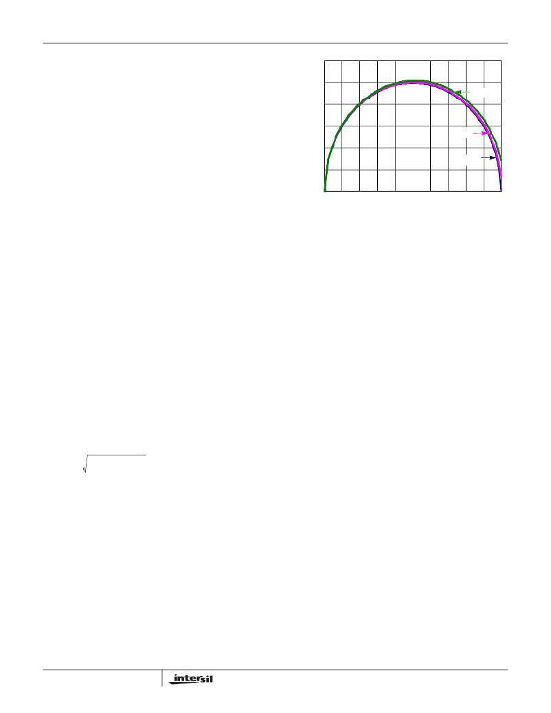
�DUTY� CYCLE� (D)�
�FIGURE� 14.� INPUT-CAPACITOR� CURRENT� MULTIPLIER� FOR�
�SINGLE-PHASE� BUCK� CONVERTER�
�For� a� through� hole� design,� several� electrolytic� capacitors�
�(Panasonic� HFQ� series� or� Nichicon� PL� series� or� Sanyo�
�MV-GX� or� equivalent)� may� be� needed.� For� surface� mount�
�designs,� solid� tantalum� capacitors� can� be� used,� but� caution�
�must� be� exercised� with� regard� to� the� capacitor� surge� current�
�rating.� These� capacitors� must� be� capable� of� handling� the�
�surge-current� at� power-up.� The� TPS� series� available� from�
�AVX,� and� the� 593D� series� from� Sprague� are� both� surge�
�current� tested.�
�MOSFET� Selection/Considerations�
�The� ISL8107� requires� a� N-Channel� power� MOSFET.� This�
�should� be� selected� based� upon� r� DS(ON)� ,� gate� supply�
�requirements,� and� thermal� management� requirements.�
�The� power� dissipation� includes� two� loss� components;�
�conduction� loss� and� switching� loss.�
�2� 1�
�2�
�Equation� 9� .�
�(EQ.� 10)�
�I� O� (� D� –� D� 2� )� +� --------� D�
�V� O�
�I� IN� ,� RMS� =�
�2� Δ� I� 2�
�12�
�D� =� ----------�
�VIN�
�where:� D� is� the� duty� cycle� =� V� O� /� V� IN� ,�
�T� SW� is� the� switching� interval,� and�
�F� s� is� the� switching� frequency.�
�OR�
�I� IN� ,� RMS� =� K� ICM� ?� I� O�
�12�
�(EQ.� 9)�
�The� gate-charge� losses� are� dissipated� by� the� ISL8107� and�
�don't� heat� the� MOSFETs.� However,� large� gate-charge�
�increases� the� switching� interval,� t� SW� which� increases� the�
�MOSFET� switching� losses.� Ensure� that� the� MOSFET� is�
�within� its� maximum� junction� temperature� at� high� ambient�
�temperature� by� calculating� the� temperature� rise� according� to�
�package� thermal-resistance� specifications.� A� separate�
�heatsink� may� be� necessary� depending� upon� MOSFET�
�power,� package� type,� ambient� temperature� and� air� flow.�
�Note� that� at� 9V� input� voltage,� the� PVCC� voltage� can� be� as�
�low� as� 6V.� Low� gate-voltage� threshold� MOSFET� must� be�
�used� in� this� condition.�
�FN6605.0�
�October� 29,� 2008�
�相关PDF资料 |
PDF描述 |
|---|---|
| AS1PKHM3/85A | DIODE STD 1.5A 800V ESMP |
| AS1PJHM3/85A | DIODE STD 1.5A 600V ESMP |
| GMC10DRTN | CONN EDGECARD 20POS DIP .100 SLD |
| AS1PGHM3/85A | DIODE STD 1.5A 400V ESMP |
| AS1PDHM3/85A | DIODE STD 1.5A 200V ESMP |
相关代理商/技术参数 |
参数描述 |
|---|---|
| ISL8107IRZ | 功能描述:IC REG CTRLR BUCK PWM VM 16-QFN RoHS:是 类别:集成电路 (IC) >> PMIC - 稳压器 - DC DC 切换控制器 系列:- 产品培训模块:Lead (SnPb) Finish for COTS Obsolescence Mitigation Program 标准包装:2,500 系列:- PWM 型:电流模式 输出数:1 频率 - 最大:275kHz 占空比:50% 电源电压:18 V ~ 110 V 降压:无 升压:无 回扫:无 反相:无 倍增器:无 除法器:无 Cuk:无 隔离:是 工作温度:-40°C ~ 85°C 封装/外壳:8-SOIC(0.154",3.90mm 宽) 包装:带卷 (TR) |
| ISL8107IRZ-T | 功能描述:IC REG CTRLR BUCK PWM VM 16-QFN RoHS:是 类别:集成电路 (IC) >> PMIC - 稳压器 - DC DC 切换控制器 系列:- 产品培训模块:Lead (SnPb) Finish for COTS Obsolescence Mitigation Program 标准包装:2,500 系列:- PWM 型:电流模式 输出数:1 频率 - 最大:275kHz 占空比:50% 电源电压:18 V ~ 110 V 降压:无 升压:无 回扫:无 反相:无 倍增器:无 除法器:无 Cuk:无 隔离:是 工作温度:-40°C ~ 85°C 封装/外壳:8-SOIC(0.154",3.90mm 宽) 包装:带卷 (TR) |
| ISL8112 | 制造商:INTERSIL 制造商全称:Intersil Corporation 功能描述:High Light-Load Efficiency, Dual-Output, Main Power Supply Controllers |
| ISL8112EVAL1Z | 功能描述:EVALUATION BOARD FOR ISL8112 RoHS:是 类别:编程器,开发系统 >> 评估板 - DC/DC 与 AC/DC(离线)SMPS 系列:- 产品培训模块:Obsolescence Mitigation Program 标准包装:1 系列:True Shutdown™ 主要目的:DC/DC,步升 输出及类型:1,非隔离 功率 - 输出:- 输出电压:- 电流 - 输出:1A 输入电压:2.5 V ~ 5.5 V 稳压器拓扑结构:升压 频率 - 开关:3MHz 板类型:完全填充 已供物品:板 已用 IC / 零件:MAX8969 |
发布紧急采购,3分钟左右您将得到回复。