- 您现在的位置:买卖IC网 > PDF目录17367 > ISL85033EVAL2Z (Intersil)EVAL BOARD2 FOR ISL85033 PDF资料下载
参数资料
| 型号: | ISL85033EVAL2Z |
| 厂商: | Intersil |
| 文件页数: | 18/26页 |
| 文件大小: | 0K |
| 描述: | EVAL BOARD2 FOR ISL85033 |
| 标准包装: | 1 |
| 系列: | * |
�� �
�
�ISL85033�
�condition� has� cleared.� If� the� overcurrent� fault� counter� overflows�
�during� soft-start,� the� converter� shuts� down� and� this� hiccup� mode�
�operation� repeats.�
�Thermal� Overload� Protection�
�Thermal� overload� protection� limits� maximum� junction�
�temperature� in� the� ISL85033.� When� the� junction� temperature�
�(T� J� )� exceeds� +150°C,� a� thermal� sensor� sends� a� signal� to� the� fault�
�monitor.�
�The� fault� monitor� commands� the� buck� regulator� to� shut� down.�
�When� the� junction� temperature� has� decreased� by� 20°C,� the�
�regulator� will� attempt� a� normal� soft-start� sequence� and� return� to�
�Synchronization� Control�
�The� frequency� of� operation� can� be� synchronized� up� to� 2MHz� by�
�an� external� signal� applied� to� the� SYNCIN� pin.� The� falling� edge� on�
�the� SYNCIN� triggers� the� rising� edge� of� PHASE1/2.� The� switching�
�frequency� for� each� output� is� half� of� the� SYNCIN� frequency.�
�Output� Inductor� Selection�
�The� inductor� value� determines� the� converter’s� ripple� current.�
�Choosing� an� inductor� current� requires� a� somewhat� arbitrary�
�choice� of� ripple� current,� Δ� I.� A� reasonable� starting� point� is� 30%� of�
�total� load� current.� The� inductor� value� can� then� be� calculated�
�using� Equation� 5:�
�V� IN� –� V� OUT� V� OUT�
�Fs� ×� Δ� I�
�normal� operation.� For� continuous� operation,� the� +125°C�
�junction� temperature� rating� should� not� be� exceeded.�
�L� =� ----------------------------� � -------------�
�V� IN�
�(EQ.� 5)�
�BOOT� Undervoltage� Protection�
�If� the� BOOT� capacitor� voltage� falls� below� 2.5V,� the� BOOT�
�undervoltage� protection� circuit� will� pull� the� phase� pin� low� through�
�a� 1� ?� switch� for� 400ns� to� recharge� the� capacitor.� This� operation�
�may� arise� during� long� periods� of� no� switching� as� in� no� load�
�situations.�
�Application� Guidelines�
�Operating� Frequency�
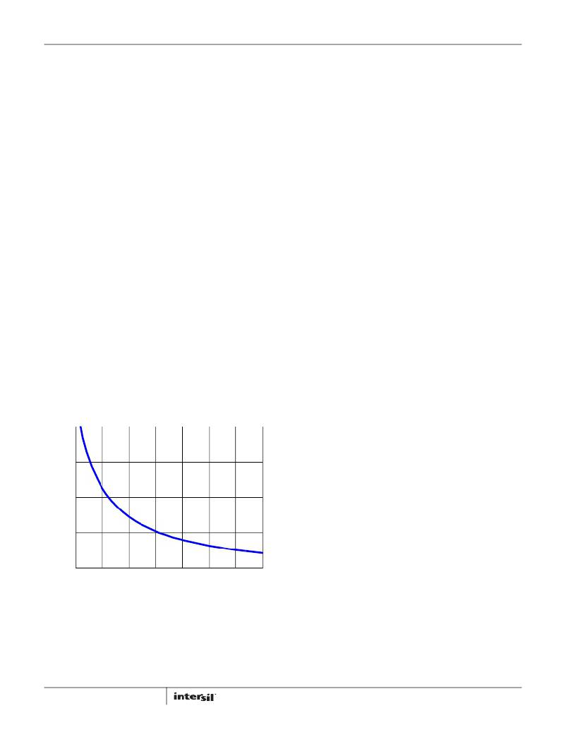
�The� ISL85033� operates� at� a� default� switching� frequency� of�
�500kHz� if� FS� is� tied� to� VCC.� Tie� a� resistor� from� FS� to� GND� to�
�program� the� switching� frequency� from� 300kHz� to� 2MHz,� as�
�Increasing� the� value� of� inductance� reduces� the� ripple� current� and�
�thus� ripple� voltage.� However,� the� larger� inductance� value� may�
�reduce� the� converter’s� response� time� to� a� load� transient.� The�
�inductor� current� rating� should� be� such� that� it� will� not� saturate� in�
�overcurrent� conditions.�
�Buck� Regulator� Output� Capacitor� Selection�
�An� output� capacitor� is� required� to� filter� the� inductor� current.�
�Output� ripple� voltage� and� transient� response� are� 2� critical� factors�
�when� considering� output� capacitance� choice.� The� current� mode�
�control� loop� allows� the� usage� of� low� ESR� ceramic� capacitors� and�
�thus� smaller� board� layout.� Electrolytic� and� polymer� capacitors�
�may� also� be� used.�
�shown� in� Equation� 4.�
�R� FS� [� k� Ω� ]� =� 122k� Ω?� (� t� –� 0.17� μ� s� )�
�Where:�
�t� is� the� switching� period� in� μs.�
�300�
�200�
�100�
�(EQ.� 4)�
�Additional� consideration� applies� to� ceramic� capacitors.� While�
�they� offer� excellent� overall� performance� and� reliability,� the� actual�
�in-circuit� capacitance� must� be� considered.� Ceramic� capacitors�
�are� rated� using� large� peak-to-peak� voltage� swings� and� with� no� DC�
�bias.� In� the� DC/DC� converter� application,� these� conditions� do� not�
�reflect� reality.� As� a� result,� the� actual� capacitance� may� be�
�considerably� lower� than� the� advertised� value.� Consult� the�
�manufacturers� data� sheet� to� determine� the� actual� in-application�
�capacitance.� Most� manufacturers� publish� capacitance� vs� DC� bias�
�so� that� this� effect� can� be� easily� accommodated.� The� effects� of�
�AC� voltage� are� not� frequently� published,� but� an� assumption� of�
�~20%� further� reduction� will� generally� suffice.� The� result� of� these�
�considerations� can� easily� result� in� an� effective� capacitance� 50%�
�lower� than� the� rated� value.� Nonetheless,� they� are� a� very� good�
�choice� in� many� applications� due� to� their� reliability� and� extremely�
�low� ESR.�
�The� following� equations� allow� calculation� of� the� required�
�capacitance� to� meet� a� desired� ripple� voltage� level.� Additional�
�capacitance� may� be� used.�
�V� OUTripple� =� -----------------------------------�
�0�
�500� 750� 1000� 1250� 1500�
�FS� (kHz)�
�FIGURE� 43.� R� FS� SELECTION� vs� FS�
�1750�
�2000�
�For� the� ceramic� capacitors� (low� ESR):� =�
�Δ� I�
�8� ?� F� SW� ?� C� OUT�
�(EQ.� 6)�
�where� Δ� I� is� the� inductor’s� peak� to� peak� ripple� current,� F� SW� is� the�
�switching� frequency� and� C� OUT� is� the� output� capacitor.�
�If� using� electrolytic� capacitors� then:�
�18�
�V� OUTripple� =� Δ� I*ESR�
�(EQ.� 7)�
�FN6676.6�
�February� 23,� 2012�
�相关PDF资料 |
PDF描述 |
|---|---|
| MIC5891BWM | IC DRVR LATCH 8BIT SER IN 16SOIC |
| MIC5891BN | IC DRVR LATCH 8BIT SER IN 16DIP |
| TAAB336K010G | CAP TANT 33UF 10V 10% AXIAL |
| SPX385AS-L-1-2 | IC VREF SHUNT PREC 1.235V 8SOICN |
| A9AAT-1105F | FLEX CABLE - AFE11T/AF11/AFE11T |
相关代理商/技术参数 |
参数描述 |
|---|---|
| ISL85033IRTZ | 功能描述:IC REG BUCK SYNC ADJ 3A 28TQFN RoHS:是 类别:集成电路 (IC) >> PMIC - 稳压器 - DC DC 开关稳压器 系列:- 产品培训模块:Lead (SnPb) Finish for COTS Obsolescence Mitigation Program 标准包装:2,500 系列:- 类型:降压(降压) 输出类型:两者兼有 输出数:1 输出电压:5V,1 V ~ 10 V 输入电压:3.5 V ~ 28 V PWM 型:电流模式 频率 - 开关:220kHz ~ 1MHz 电流 - 输出:600mA 同步整流器:无 工作温度:-40°C ~ 125°C 安装类型:表面贴装 封装/外壳:16-SSOP(0.154",3.90mm 宽) 包装:带卷 (TR) 供应商设备封装:16-QSOP |
| ISL85033IRTZ-T | 功能描述:IC REG BUCK SYNC ADJ 3A 28TQFN RoHS:是 类别:集成电路 (IC) >> PMIC - 稳压器 - DC DC 开关稳压器 系列:- 产品培训模块:Lead (SnPb) Finish for COTS Obsolescence Mitigation Program 标准包装:2,500 系列:- 类型:降压(降压) 输出类型:两者兼有 输出数:1 输出电压:5V,1 V ~ 10 V 输入电压:3.5 V ~ 28 V PWM 型:电流模式 频率 - 开关:220kHz ~ 1MHz 电流 - 输出:600mA 同步整流器:无 工作温度:-40°C ~ 125°C 安装类型:表面贴装 封装/外壳:16-SSOP(0.154",3.90mm 宽) 包装:带卷 (TR) 供应商设备封装:16-QSOP |
| ISL85033IRTZ-T7A | 功能描述:直流/直流开关调节器 3A STD BUCK REG - 4X 4 TQFN 250 PC REEL RoHS:否 制造商:International Rectifier 最大输入电压:21 V 开关频率:1.5 MHz 输出电压:0.5 V to 0.86 V 输出电流:4 A 输出端数量: 最大工作温度: 安装风格:SMD/SMT 封装 / 箱体:PQFN 4 x 5 |
| ISL8505IRZ | 制造商:Intersil Corporation 功能描述:PB-FREE DC TO DC POWER SWITCHING, 38LD QFN 5X7 - Rail/Tube |
| ISL8510EVAL1Z | 功能描述:EVALUATION BOARD FOR ISL8510 RoHS:是 类别:编程器,开发系统 >> 评估板 - DC/DC 与 AC/DC(离线)SMPS 系列:- 产品培训模块:Obsolescence Mitigation Program 标准包装:1 系列:True Shutdown™ 主要目的:DC/DC,步升 输出及类型:1,非隔离 功率 - 输出:- 输出电压:- 电流 - 输出:1A 输入电压:2.5 V ~ 5.5 V 稳压器拓扑结构:升压 频率 - 开关:3MHz 板类型:完全填充 已供物品:板 已用 IC / 零件:MAX8969 |
发布紧急采购,3分钟左右您将得到回复。