参数资料
| 型号: | ISL9443IRZ-T7A |
| 厂商: | Intersil |
| 文件页数: | 3/23页 |
| 文件大小: | 0K |
| 描述: | IC REG CTRLR BUCK PWM CM 32-QFN |
| 标准包装: | 1 |
| PWM 型: | 电流模式 |
| 输出数: | 3 |
| 频率 - 最大: | 1.32MHz |
| 电源电压: | 4.5 V ~ 26 V |
| 降压: | 是 |
| 升压: | 无 |
| 回扫: | 无 |
| 反相: | 无 |
| 倍增器: | 无 |
| 除法器: | 无 |
| Cuk: | 无 |
| 隔离: | 无 |
| 工作温度: | -40°C ~ 85°C |
| 封装/外壳: | 32-VFQFN 裸露焊盘 |
| 包装: | 标准包装 |
| 其它名称: | ISL9443IRZ-T7ADKR |
�� �
�
�ISL9443�
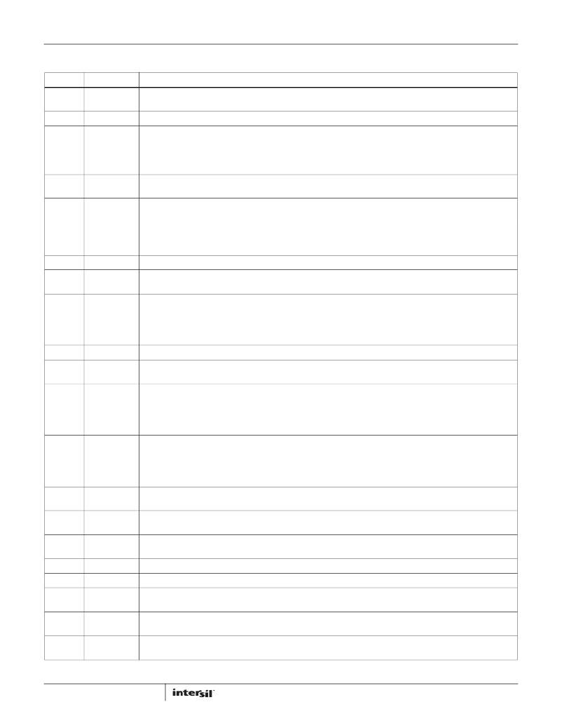
�Pin� Descriptions�
�(Continued)�
�PIN�
�5�
�6�
�7�
�8�
�9�
�10�
�11�
�12�
�13�
�14�
�15�
�16�
�17�
�18�
�19�
�20�
�21�
�22�
�23�
�24�
�25�
�NAME�
�FB1�
�OCSET1�
�RT�
�PGOOD�
�EN23�
�SGND�
�OCSET2�
�FB2�
�TK/SS2�
�OCSET3�
�FB3�
�TK/SS3�
�MODE/SYNC�
�ISEN3�
�PHASE3�
�BOOT3�
�UGATE3�
�LGATE3�
�PGND�
�ISEN2�
�PHASE2�
�FUNCTION�
�PWM1� feedback� input.� Connect� FB1� to� a� resistive� voltage� divider� from� the� output� of� PWM1� to� GND� to� adjust� the� output�
�voltage.�
�A� resistor� from� this� pin� to� ground� adjusts� the� overcurrent� threshold� for� PWM1.�
�A� resistor� from� this� pin� to� ground� adjusts� the� switching� frequency� from� 200kHz� to� 1.2MHz.�
�R� T� =� (� 23.36� ×� (� 1.5� ×� t� SW� –� 0.36� )� )� ?� k� Ω�
�(EQ.� 1)�
�Where� t� SW� is� the� switching� period� in� μs.�
�Open� drain� logic� output� used� to� indicate� the� status� of� the� PWM� output� voltages.� This� pin� is� pulled� LOW� when� any� of� the�
�outputs� is� not� within� ±11%� of� the� nominal� voltage.�
�Enable/Disable� input� for� PWM2� and� PWM3.� The� outputs� of� PWM2� and� PWM3� are� enabled� when� this� pin� is� pulled� HIGH,�
�and� disabled� when� this� pin� is� pulled� LOW.� Do� not� float� this� pin.�
�This� is� the� small-signal� ground� common� to� all� 3� controllers.� It� is� suggested� to� route� this� separately� from� the� high� current�
�ground� (PGND).� SGND� and� PGND� can� be� tied� together� if� there� is� one� solid� ground� plane� with� no� noisy� currents� around�
�the� chip.� All� voltage� levels� are� measured� with� respect� to� this� pin.�
�A� resistor� from� this� pin� to� ground� adjusts� the� overcurrent� threshold� for� PWM2.�
�PWM2� feedback� input.� Connect� FB2� to� a� resistive� voltage� divider� from� the� output� of� PWM2� to� GND� to� adjust� the� output�
�voltage.�
�Dual� function� pin.� The� reference� voltage� of� PWM2� is� clamped� to� the� voltage� at� TK/SS2� during� start-up.� When� this� pin� is�
�used� for� tracking,� another� channel� is� configured� as� the� master� and� the� output� voltage� of� the� master� channel� is� applied�
�to� this� pin� via� a� resistor� divider.�
�When� used� for� soft-starting� control,� a� soft-start� capacitor� is� connected� from� this� pin� to� GND.� A� regulated� 1.55μA� soft-starting�
�current� charges� up� the� soft-start� capacitor.� Value� of� the� soft-start� capacitor� sets� the� PWM2� output� voltage� ramp.�
�A� resistor� from� this� pin� to� ground� adjusts� the� overcurrent� threshold� for� PWM3.�
�PWM3� feedback� input.� Connect� FB3� to� a� resistive� voltage� divider� from� the� output� of� PWM3� to� GND� to� adjust� the� output�
�voltage.�
�Dual� function� pin.� The� reference� voltage� of� PWM3� is� clamped� to� the� voltage� at� TK/SS3� during� start-up.� When� this� pin� is�
�used� for� tracking,� another� channel� is� configured� as� the� master� and� the� output� voltage� of� the� master� channel� is� applied�
�to� this� pin� via� a� resistor� divider.�
�When� used� for� soft-starting� control,� a� soft-start� capacitor� is� connected� from� this� pin� to� GND.� A� regulated� 1.55μA� soft-starting�
�current� charges� up� the� soft-start� capacitor.� Value� of� the� soft-start� capacitor� sets� the� PWM3� output� voltage� ramp.�
�Dual� function� pin.� Tie� this� pin� to� ground� or� VCC_5V� for� DEM� or� CCM� operation� mode� selection.� Connect� this� pin� to� ground�
�to� select� Diode� Emulation� Mode� with� pulse� skipping� at� light� load.� While� connected� to� VCC_5V,� the� controllers� operate� in�
�PWM� Mode� at� light� load.�
�Connect� this� pin� to� an� external� clock� for� synchronization.� The� controller� operates� in� PWM� mode� at� light� load� when�
�synchronized� with� an� external� clock.�
�Current� signal� input� for� PWM3.� This� pin� is� used� to� monitor� the� voltage� drop� across� the� lower� MOSFET� for� current� loop�
�feedback� and� overcurrent� protection.�
�Phase� node� connection� for� PWM3.� This� pin� is� connected� to� the� junction� of� the� upper� MOSFET’s� source,� output� filter� inductor,�
�and� lower� MOSFET’s� drain.� PHASE3� is� the� internal� lower� supply� rail� for� UGATE3.�
�Bootstrap� pin� to� provide� bias� for� PWM3� high-side� driver.� The� positive� terminal� of� the� bootstrap� capacitor� connects� to� this�
�pin.� The� bootstrap� diodes� are� integrated� to� help� reduce� total� cost� and� reduce� layout� complexity.�
�High-side� MOSFET� gate� driver� output� for� PWM3.�
�Low-side� MOSFET� gate� driver� output� for� PWM3.�
�Power� ground� connection� for� all� three� PWM� channels.� This� pin� should� be� connected� to� the� sources� of� the� lower� MOSFETs�
�and� the� (-)� terminals� of� the� external� input� capacitors�
�Current� signal� input� for� PWM2.� This� pin� is� used� to� monitor� the� voltage� drop� across� the� lower� MOSFET� for� current� loop�
�feedback� and� overcurrent� protection.�
�Phase� node� connection� for� PWM2.� This� pin� is� connected� to� the� junction� of� the� upper� MOSFET’s� source,� output� filter� inductor,�
�and� lower� MOSFET’s� drain.� PHASE2� is� the� internal� lower� supply� rail� for� UGATE2.�
�3�
�FN7663.1�
�February� 24,� 2012�
�相关PDF资料 |
PDF描述 |
|---|---|
| ISL9444IRZ | IC REG CTRLR BUCK PWM CM 40-QFN |
| ISL9491ERZ | IC REG SGL LNB CONTROL 16QFN |
| ISL9492ERZ-T | IC REG SGL LNB CONTROL 28TQFN |
| ISL9506HRZ | IC REG CTRLR BUCK PWM 40-QFN |
| ISL95210IRZ | IC REG BUCK SYNC ADJ 10A 32QFN |
相关代理商/技术参数 |
参数描述 |
|---|---|
| ISL9443IRZ-T7AS2750 | 制造商:Intersil Corporation 功能描述:ISL9443 TRIPLE, STEP- DOWN PWM CONTROLLER IMVP-6. 32 LD MLFP - Tape and Reel |
| ISL9443IRZ-TS2750 | 制造商:Intersil Corporation 功能描述:PB FREE. ISL9443 TRIPLE, STEP- DOWN PWM CONTROLLER IMVP-6. 3 - Tape and Reel |
| ISL9444CRZ | 制造商:Intersil Corporation 功能描述:PB FREE. ISL9444 TRIPLE, STEP- DOWN PWM CONTROLLER IMVP-6. 4 - Rail/Tube 制造商:Intersil Corporation 功能描述:IC REG CTRLR BUCK PWM CM 32-QFN 制造商:Intersil 功能描述:Pb Free. ISL9444 Tri ple, Step- Down PWM |
| ISL9444CRZ-T | 制造商:Intersil Corporation 功能描述:PB FREE. ISL9444 TRIPLE, STEP- DOWN PWM CONTROLLER IMVP-6. 4 - Tape and Reel 制造商:Intersil Corporation 功能描述:IC REG CTRLR BUCK PWM CM 32-QFN 制造商:Intersil 功能描述:Pb Free. ISL9444 Tri ple, Step- Down PWM |
| ISL9444CRZ-T7A | 制造商:Intersil Corporation 功能描述:IC REG CTRLR BUCK PWM CM 32-QFN 制造商:INTERSIL 功能描述:ISL9444 Series 1.2 Mhz Triple Synchronous Step-Down PWM - QFN-40 制造商:Intersil 功能描述:ISL9444 Triple, Step - Down PWM Controlle 制造商:Intersil 功能描述:ISL9444 Series 1.2 Mhz Triple Synchronous Step-Down PWM - QFN-40 |
发布紧急采购,3分钟左右您将得到回复。