- 您现在的位置:买卖IC网 > PDF目录16590 > ISL97652IRZ-T (Intersil)IC LCD SUPPLY 4CH DUAL AMP 48QFN PDF资料下载
参数资料
| 型号: | ISL97652IRZ-T |
| 厂商: | Intersil |
| 文件页数: | 14/25页 |
| 文件大小: | 0K |
| 描述: | IC LCD SUPPLY 4CH DUAL AMP 48QFN |
| 标准包装: | 4,000 |
| 应用: | LCD 电视机/监控器 |
| 电流 - 电源: | 500µA |
| 电源电压: | 8 V ~ 15 V |
| 工作温度: | -40°C ~ 85°C |
| 安装类型: | 表面贴装 |
| 封装/外壳: | 48-VFQFN 裸露焊盘 |
| 供应商设备封装: | 48-QFN(7x7) |
| 包装: | 带卷 (TR) |
�� �
�
�ISL97652�
�chip.� Therefore,� three� separate� fault� mechanisms� are�
�operated.�
�1.� The� SWO� output� range� is� constantly� monitored� and�
�Feedback� Resistors�
�The� buck� converter� output� voltage� is� determined� by� the�
�following� equation:�
�V� LOGIC� =� ---------------------------� � V� FBB�
�expected� to� rise� if� the� PFET� is� in� current� limit.� The� rate� of�
�rise� at� SWO� can� be� calculated� from� the� current� limit� and�
�the� capacitance� on� SWO� by� using� the� equation�
�R� 11� +� R� 12�
�R� 12�
�(EQ.� 11)�
�dV/dt� =� Ilimit/Cavdd.� The� SWO� voltage� range� is� split� into�
�sections� of� approximately� 0.7V� such� that� every� time� the�
�output� rises� by� this� amount� the� circuit� detects� that� the�
�voltage� is� rising.� Should� the� circuit� remain� in� current� limit�
�for� more� than� 100μs� with� no� such� rise� taking� place� the�
�circuit� will� fault� out.� In� this� scenario,� the� PFET� will�
�immediately� switch� itself� off� and� the� rest� of� the� ISL97652�
�will� later� fault� out� due� to� the� boost� voltage� at� A� VDD� falling�
�away.�
�2.� As� well� as� monitoring� any� rise� in� the� voltage� at� SWO,� the�
�circuit� also� monitors� any� falls� in� this� level.� If� the� output�
�falls� by� more� than� a� certain� amount� while� it� is� in� current�
�limit� the� circuit� will� fault� out� immediately.� This� amount�
�Where� R11� and� R12� are� the� feedback� resistors� of� buck�
�converter� to� set� the� output� voltage.� Current� drawn� by� the�
�resistor� network� should� be� limited� to� maintain� the� overall�
�converter� efficiency.� The� maximum� value� of� the� resistor�
�network� is� limited� by� the� feedback� input� bias� current� and� the�
�potential� for� noise� being� coupled� into� the� feedback� pin.� A�
�resistor� network� in� the� order� of� 1k� Ω� is� recommended.�
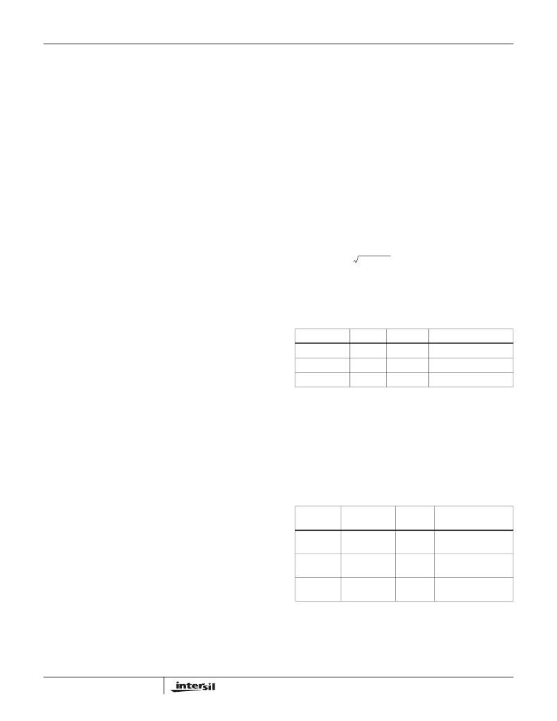
�Buck� Converter� Input� Capacitor�
�The� capacitor� should� support� the� maximum� AC� RMS� current�
�which� happens� when� D� =� 0.5� and� maximum� output� current.�
�varies� from� about� 1V� to� about� 1.4V� depending� on� the�
�output� level� before� the� fall.� In� this� scenario,� the� PFET� will�
�I� ACRMS� (� C� IN� )� =�
�D� ?� (� 1� –� D� )� ?� I� O�
�(EQ.� 12)�
�immediately� switch� itself� off� and� the� rest� of� the� ISL97652�
�will� later� fault� out� due� to� the� boost� voltage� falling� away.�
�3.� Once� the� ISL97652� has� successfully� sequenced� the�
�boost� on� and� the� boost� soft-start� capacitor� has� charged�
�up,� a� third� fault� check� is� also� added.� After� this� point� if� the�
�Where� I� o� is� the� output� current� of� the� buck� converter.� The�
�following� table� shows� some� recommendations� for� input�
�capacitor.�
�TABLE� 6.� INPUT� CAPACITOR� (BUCK)� RECOMMENDATION�
�PFET� enters� current� limit� for� greater� than� the� global�
�timeout� of� 40μs� then� the� chip� will� fault� out.� In� this� scenario�
�the� whole� chip� will� be� disabled� with� the� PFET�
�immediately� switched� off.�
�Buck� Converter�
�CAPACITOR�
�10μF/16V�
�10μF/10V�
�22μF/16V�
�SIZE�
�1206�
�0805�
�1210�
�VENDOR�
�TDK�
�Murata�
�Murata�
�PART� NUMBER�
�C3216X7R1C106M�
�GRM21BR61A106K�
�C3225X7R1C226M�
�The� buck� converter� is� the� step� down� converter,� which�
�supplies� the� current� to� the� logic� circuit� of� the� LCD� system.�
�The� ISL97652� integrates� an� 20V� N-Channel� MOSFET� to�
�save� cost� and� reduce� external� component� count.� In� the�
�continuous� current� mode,� the� relationship� between� input�
�voltage� and� output� voltage� is� as� follows:�
�Buck� Inductor�
�A� 3.3μH� to� 10μH� inductor� is� the� good� choice� for� the� buck�
�converter.� Besides� the� inductance,� the� DC� resistance� and�
�the� saturation� current� are� also� the� factor� needed� to� be�
�considered� when� choosing� buck� inductor.� Low� DC�
�V� LOGIC�
�----------------------� =� D�
�V� IN�
�(EQ.� 8)�
�resistance� can� help� maintain� high� efficiency,� and� the�
�saturation� current� rating� should� be� 2.5A.� Here� are� some�
�Where� D� is� the� duty� cycle� of� the� switching� MOSFET.�
�Because� D� is� always� less� than� 1,� the� output� voltage� of� buck�
�converter� is� lower� than� input� voltage.�
�recommendations� for� buck� inductor.�
�TABLE� 7.� BUCK� INDUCTOR� RECOMMENDATION�
�DIMENSIONS�
�The� peak� current� limit� of� buck� converter� is� set� to� 2.5A,� which�
�restricts� the� maximum� output� current� (average)� based� on� the�
�INDUCTOR�
�4.7μH/�
�(mm)�
�5.7x5.0x4.7�
�VENDOR�
�Murata�
�PART� NUMBER�
�LQH55DN4R7M01K�
�following� equation:�
�2.7A� PEAK�
�I� OMAX� =� 2.5A� –� Δ� I� PP�
�(EQ.� 9)�
�6.8μH/�
�3A� PEAK�
�7.3x6.8x3.2�
�TDK�
�RLF7030T-6R8M2R8�
�Where� Δ� I� PP� is� the� ripple� current� in� the� buck� inductor� as� the�
�following� equation:�
�10μH/�
�2.4A� PEAK�
�12.95x9.4x3.0� Coilcraft�
�DO3308P-103�
�Δ� I� PP� =� ----------------------� ?� (� 1� –� D� )�
�V� LOGIC�
�L� ?� f� s�
�(EQ.� 10)�
�Rectifier� Diode� (Buck� Converter)�
�Where� L� is� the� buck� inductor,� f� s� is� the� switching� frequency.�
�14�
�A� Schottky� diode� is� recommended� due� to� fast� recovery� and� low�
�forward� voltage.� The� reverse� voltage� rating� should� be� higher�
�FN9287.1�
�November� 2,� 2007�
�相关PDF资料 |
PDF描述 |
|---|---|
| H3DKH-3418G | IDC CABLE - HKR34H/AE34G/HPK34H |
| AK670M/2-2-GR-R | CABLE USB A-MINI B 4PIN V2.0 2M |
| EEM15DSEF | CONN EDGECARD 30POS .156 EYELET |
| 446074-1 | LGH 1/2 DBL MLD END |
| RCM15DRTS | CONN EDGECARD 30POS DIP .156 SLD |
相关代理商/技术参数 |
参数描述 |
|---|---|
| ISL97652IRZ-TK | 功能描述:IC LCD SUPPLY 4CH DUAL AMP 48QFN RoHS:是 类别:集成电路 (IC) >> PMIC - 电源管理 - 专用 系列:- 应用说明:Ultrasound Imaging Systems Application Note 产品培训模块:Lead (SnPb) Finish for COTS Obsolescence Mitigation Program 标准包装:37 系列:- 应用:医疗用超声波成像,声纳 电流 - 电源:- 电源电压:2.37 V ~ 6 V 工作温度:0°C ~ 70°C 安装类型:表面贴装 封装/外壳:56-WFQFN 裸露焊盘 供应商设备封装:56-TQFN-EP(8x8) 包装:管件 |
| ISL97653AIRZ | 功能描述:电流型 PWM 控制器 5-CH INTEGRTD LCD SUPPLY W/TEMP SENSOR RoHS:否 制造商:Texas Instruments 开关频率:27 KHz 上升时间: 下降时间: 工作电源电压:6 V to 15 V 工作电源电流:1.5 mA 输出端数量:1 最大工作温度:+ 105 C 安装风格:SMD/SMT 封装 / 箱体:TSSOP-14 |
| ISL97653AIRZ-T | 功能描述:电流型 PWM 控制器 5-CH INTEGRTD LCD SUPPLY W/TEMP SENSOR RoHS:否 制造商:Texas Instruments 开关频率:27 KHz 上升时间: 下降时间: 工作电源电压:6 V to 15 V 工作电源电流:1.5 mA 输出端数量:1 最大工作温度:+ 105 C 安装风格:SMD/SMT 封装 / 箱体:TSSOP-14 |
| ISL97653AIRZ-TK | 功能描述:电流型 PWM 控制器 5-CH INTEGRTD LCD SUPPLY W/TEMP SENSOR RoHS:否 制造商:Texas Instruments 开关频率:27 KHz 上升时间: 下降时间: 工作电源电压:6 V to 15 V 工作电源电流:1.5 mA 输出端数量:1 最大工作温度:+ 105 C 安装风格:SMD/SMT 封装 / 箱体:TSSOP-14 |
| ISL97653IRZ | 制造商:Intersil Corporation 功能描述: |
发布紧急采购,3分钟左右您将得到回复。