- 您现在的位置:买卖IC网 > PDF目录16590 > ISL97652IRZ-T (Intersil)IC LCD SUPPLY 4CH DUAL AMP 48QFN PDF资料下载
参数资料
| 型号: | ISL97652IRZ-T |
| 厂商: | Intersil |
| 文件页数: | 15/25页 |
| 文件大小: | 0K |
| 描述: | IC LCD SUPPLY 4CH DUAL AMP 48QFN |
| 标准包装: | 4,000 |
| 应用: | LCD 电视机/监控器 |
| 电流 - 电源: | 500µA |
| 电源电压: | 8 V ~ 15 V |
| 工作温度: | -40°C ~ 85°C |
| 安装类型: | 表面贴装 |
| 封装/外壳: | 48-VFQFN 裸露焊盘 |
| 供应商设备封装: | 48-QFN(7x7) |
| 包装: | 带卷 (TR) |
�� �
�
�ISL97652�
�than� the� maximum� input� voltage.� The� peak� current� rating� is� 2A,�
�and� the� average� current� should� be� as� the� following� equation,�
�Regulated� Charge� Pump� Controllers� (V� ON� and�
�V� OFF� )�
�I� AVG� =� (� 1� –� D� )� *I� o�
�(EQ.� 13)�
�The� ISL97652� includes� 2� independent� charge� pumps� (see�
�charge� pump� block� and� connection� diagram).� The� negative�
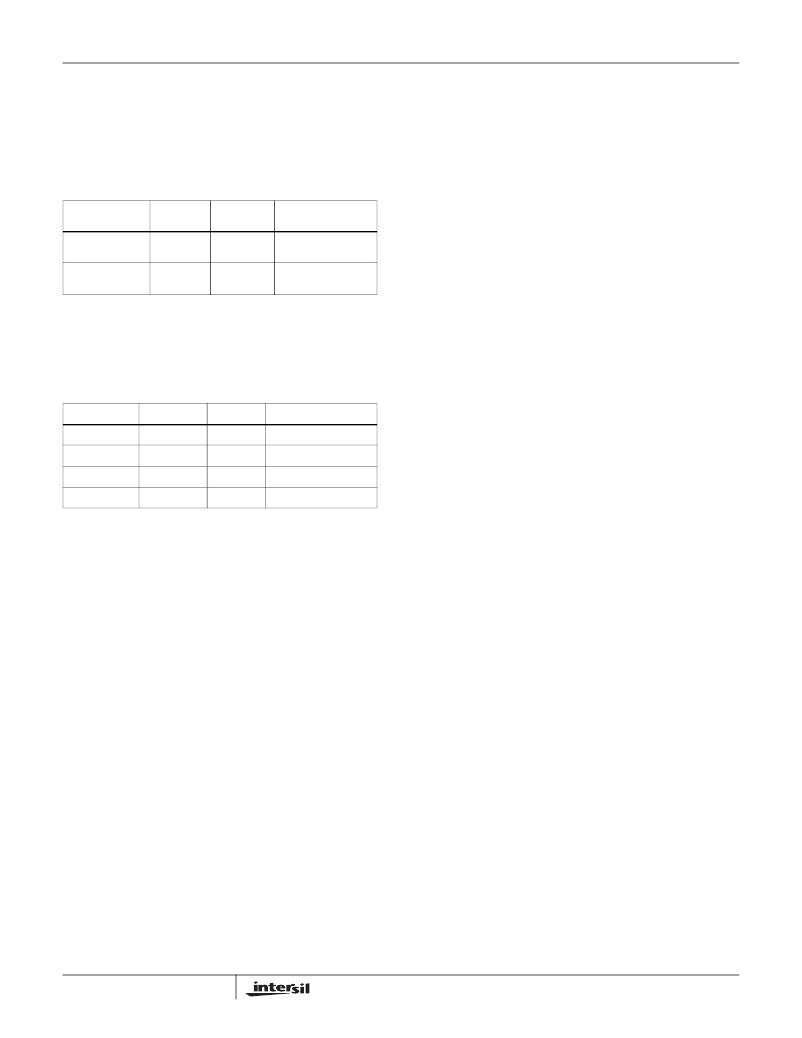
�Where� I� o� is� the� output� current� of� buck� converter.� The�
�following� table� shows� some� diode� recommended.�
�TABLE� 8.� BUCK� RECTIFIER� DIODE� RECOMMENDATION�
�charge� pump� inverters� the� V� SUP� voltage� and� provides� a�
�regulated� negative� output� voltage.� The� positive� charge� pump�
�doubles� or� triples� the� V� SUP� voltage� and� provided� a� regulated�
�positive� output� voltage.� The� regulation� of� both� the� negative�
�DIODE�
�PMEG2020EJ�
�SS22�
�V� R� /I� AVG�
�RATING�
�20V/2A�
�20V/2A�
�PACKAGE�
�SOD323F�
�SMB�
�VENDOR�
�Philips�
�Semiconductors�
�Fairchild�
�and� positive� charge� pumps� is� generated� by� internal�
�comparator� that� senses� the� output� voltage� and� compares� it�
�with� the� internal� reference.�
�The� pumps� use� pulse� width� modulation� to� adjust� the� pump�
�Semiconductor�
�Output� Capacitor� (Buck� Converter)�
�Four� 10μF� or� two� 22μF� ceramic� capacitors� are� recommended�
�for� this� part.� The� overshoot� and� undershoot� will� be� reduced�
�with� more� capacitance,� but� the� recovery� time� will� be� longer.�
�TABLE� 9.� BUCK� OUTPUT� CAPACITOR� RECOMMENDATION�
�period,� depending� on� the� load� present.� The� pumps� can�
�provide� 30mA� for� V� OFF� and� 20mA� for� V� ON� .�
�Positive� Charge� Pump� Design� Consideration�
�The� positive� charge� pump� can� drive� multiple� stages� for� 2X/�
�3X� step� up� ratios,� or� higher.� Internal� switches� (M1� and� M2)�
�drive� external� steering� diodes� via� the� pump� capacitor� CP.�
�Figure� 18A� shows� 2X� configuration� and� Figure� 18B� shows�
�CAPACITOR�
�10μF/6.3V�
�10μF/6.3V�
�22μF/6.3V�
�100μF/6.3V�
�SIZE�
�0805�
�0805�
�1210�
�1206�
�VENDOR�
�TDK�
�Murata�
�TDK�
�Murata�
�PART� NUMBER�
�C2012X5R0J106M�
�GRM21BR60J106K�
�C3216X5R0J226M�
�GRM31CR60J107M�
�3X� configuration.� The� output� voltage� is� divided� by� feedback�
�resistors� R7� and� R8,� which� is� then� compared� to� the� internal�
�reference� via� comparator� A1.� The� maximum� V� ON� charge�
�pump� current� can� be� estimated� from� the� following� equations�
�assuming� a� 50%� switching� duty:�
�I� MAX� (� 2x� )� ~� min� of� 50mA� or�
�2� ?� V� SUP� –� 2� ?� V� DIODE� (� 2� ?� I� MAX� )� –� V� (� V� ON� )�
�(� 2� ?� (� R� ONH� +� R� ONL� )� )�
�3� ?� V� SUP� –� 4� ?� V� DIODE� (� 2� ?� I� MAX� )� –� V� (� V� ON� )�
�4� ?� (� R� ONH� +� R� ONL� )�
�PI� Loop� Compensation� (Buck� Converter)�
�The� buck� converter� of� ISL97652� can� be� compensated� by� a�
�RC� network� connected� from� VCB� pin� to� ground.� C� CB� =� 4.7nF�
�and� R� CB� =� 10k� RC� network� is� used� in� the� demo� board.� The�
�larger� value� resistor� can� lower� the� transient� overshoot,�
�however,� at� the� expense� of� stability� of� the� loop.�
�The� stability� can� be� optimized� in� a� similar� manner� to� that�
�described� in� the� section� on� "PI� Loop� Compensation� (Boost�
�Converter)”.�
�Bootstrap� Capacitor� (C� B� )�
�This� capacitor� is� used� to� provide� the� supply� to� the� high� driver�
�circuitry� for� the� buck� MOSFET.� The� bootstrap� supply� is�
�formed� by� an� internal� diode� and� capacitor� combination.� A�
�470nF� is� recommended� for� ISL97652.� A� low� value� capacitor�
�can� lead� to� overcharging� and� in� turn� damage� the� part.�
�If� the� load� is� too� light,� the� on-time� of� the� low� side� diode� may�
�be� insufficient� to� replenish� the� bootstrap� capacitor� voltage.�
�In� this� case,� if� V� IN� -V� BUCK� <1.5V,� the� internal� MOSFET�
�pull-up� device� may� be� unable� to� turn-on� until� V� LOGIC� falls.�
�Hence,� there� is� a� minimum� load� requirement� in� this� case.�
�The� minimum� load� can� be� adjusted� by� the� feedback�
�resistors� to� FBB.�
�15�
�----------------------------------------------------------------------------------------------------------------------� ?� 0.95A�
�(EQ.� 14)�
�I� MAX� (� 3x� )� ~� min� of� 50mA� or�
�----------------------------------------------------------------------------------------------------------------------� ?� 0.95A�
�FN9287.1�
�November� 2,� 2007�
�相关PDF资料 |
PDF描述 |
|---|---|
| H3DKH-3418G | IDC CABLE - HKR34H/AE34G/HPK34H |
| AK670M/2-2-GR-R | CABLE USB A-MINI B 4PIN V2.0 2M |
| EEM15DSEF | CONN EDGECARD 30POS .156 EYELET |
| 446074-1 | LGH 1/2 DBL MLD END |
| RCM15DRTS | CONN EDGECARD 30POS DIP .156 SLD |
相关代理商/技术参数 |
参数描述 |
|---|---|
| ISL97652IRZ-TK | 功能描述:IC LCD SUPPLY 4CH DUAL AMP 48QFN RoHS:是 类别:集成电路 (IC) >> PMIC - 电源管理 - 专用 系列:- 应用说明:Ultrasound Imaging Systems Application Note 产品培训模块:Lead (SnPb) Finish for COTS Obsolescence Mitigation Program 标准包装:37 系列:- 应用:医疗用超声波成像,声纳 电流 - 电源:- 电源电压:2.37 V ~ 6 V 工作温度:0°C ~ 70°C 安装类型:表面贴装 封装/外壳:56-WFQFN 裸露焊盘 供应商设备封装:56-TQFN-EP(8x8) 包装:管件 |
| ISL97653AIRZ | 功能描述:电流型 PWM 控制器 5-CH INTEGRTD LCD SUPPLY W/TEMP SENSOR RoHS:否 制造商:Texas Instruments 开关频率:27 KHz 上升时间: 下降时间: 工作电源电压:6 V to 15 V 工作电源电流:1.5 mA 输出端数量:1 最大工作温度:+ 105 C 安装风格:SMD/SMT 封装 / 箱体:TSSOP-14 |
| ISL97653AIRZ-T | 功能描述:电流型 PWM 控制器 5-CH INTEGRTD LCD SUPPLY W/TEMP SENSOR RoHS:否 制造商:Texas Instruments 开关频率:27 KHz 上升时间: 下降时间: 工作电源电压:6 V to 15 V 工作电源电流:1.5 mA 输出端数量:1 最大工作温度:+ 105 C 安装风格:SMD/SMT 封装 / 箱体:TSSOP-14 |
| ISL97653AIRZ-TK | 功能描述:电流型 PWM 控制器 5-CH INTEGRTD LCD SUPPLY W/TEMP SENSOR RoHS:否 制造商:Texas Instruments 开关频率:27 KHz 上升时间: 下降时间: 工作电源电压:6 V to 15 V 工作电源电流:1.5 mA 输出端数量:1 最大工作温度:+ 105 C 安装风格:SMD/SMT 封装 / 箱体:TSSOP-14 |
| ISL97653IRZ | 制造商:Intersil Corporation 功能描述: |
发布紧急采购,3分钟左右您将得到回复。