- 您现在的位置:买卖IC网 > PDF目录15794 > KIT33993DWBEVB (Freescale Semiconductor)KIT EVAL FOR MC33993 SWITCH DET PDF资料下载
参数资料
| 型号: | KIT33993DWBEVB |
| 厂商: | Freescale Semiconductor |
| 文件页数: | 15/28页 |
| 文件大小: | 0K |
| 描述: | KIT EVAL FOR MC33993 SWITCH DET |
| 标准包装: | 1 |
| 类型: | 微控制器 |
| 适用于相关产品: | MC33993 |
| 所含物品: | 评估板、数据表和说明文档 |
第1页第2页第3页第4页第5页第6页第7页第8页第9页第10页第11页第12页第13页第14页当前第15页第16页第17页第18页第19页第20页第21页第22页第23页第24页第25页第26页第27页第28页
Analog Integrated Circuit Device Data
22
Freescale Semiconductor
33993
TYPICAL APPLICATIONS
INTRODUCTION
ARCHIVE
INFORMATION
ARCHIVE
INFORMATION
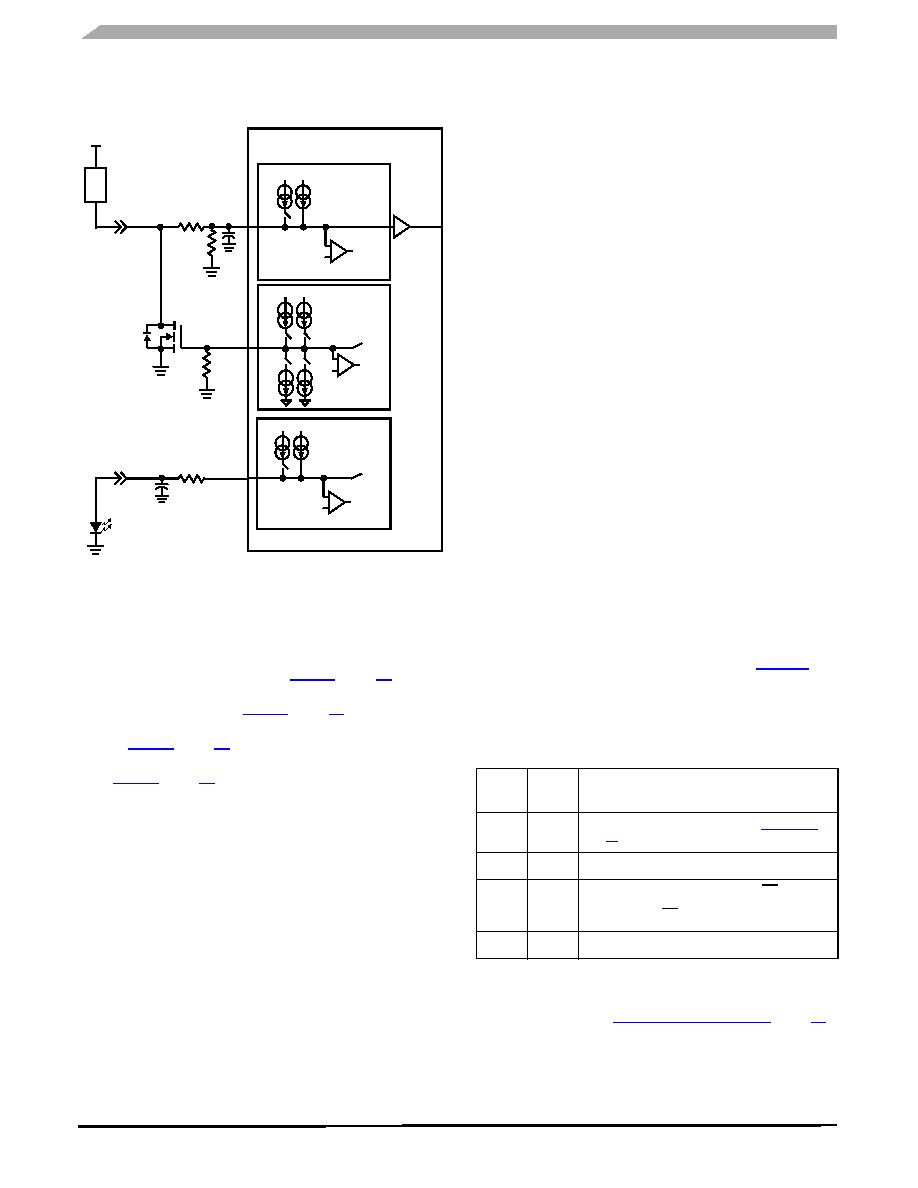
Figure 14. MOSFET or LED Driver Output
The sequence of commands (from Normal mode with
inputs tri-state) required to set up the device to drive a
MOSFET are as follows:
wetting current timer enable command –Disable SPn
metallic command –Set SPn to 16 mA or 2.0 mA gate
settings command –Set SPn as switch-to-battery (refer
tri-state command –Disable tri-state for SPn (refer to
After the tri-state command has been sent (tri-state
disable), the MOSFET gate will be pulled to ground. From this
point forward the MOSFET may be turned on and off by
sending the settings command:
settings command –SPn as switch-to-ground
(MOSFET ON)
settings command –SPn as switch-to-battery
(MOSFET OFF)
Monitoring of the MOSFET drain in the OFF state provides
open load detection. This is done by using an SGn input
comparator. With the SGn input in tri-state, the load will pull
up the SGn input to battery. With open load the SGn pin is
pulled down to ground through an external resistor. The open
load is indicated by a logic [1] in the SO data bit.
The analog command may be used to monitor the drain
voltage in the MOSFET ON state. By sourcing 2.0 mA of
current to the 1.5 k
Ω resistor, the analog voltage on the SGn
pin will be approximately:
As the voltage on the drain of the MOSFET increases, so
does the voltage on the SGn pin. With the SGn pin selected
as analog, the MCU may perform the A/D conversion.
Using this method for controlling unclamped inductive
loads is not recommended. Inductive flyback voltages greater
than VPWR may damage the IC.
The SP0–SP7 pins of this device may also be used to
send signals from one module to another. Operation is similar
to the gate control of a MOSFET.
For LED applications a resistor in series with the LED is
recommended but not required. The switch-to-ground inputs
are recommended for LED application. To drive the LED use
the following commands:
wetting current timer enable command –Disable SGn
wetting current timer
metallic command –Set SGn to 16 mA
From this point forward the LED may be turned on and off
using the tri-state command:
tri-state command –Disable tri-state for SGn (LED ON)
tri-state command –Enable tri-state for SGn (LED OFF)
These parameters are easily programmed via SPI
commands in Normal mode.
MULTIPLE 33993 DEVICES IN A MODULE SYSTEM
Connecting power to the 33993 and the MCU for Sleep
mode operation may be done in several ways. Table 20
shows several system configurations for power between the
MCU and the 33993 and their specific requirements for
functionality.
Multiple 33993 devices may be used in a module system.
SPI control may be done in parallel or serial. However when
parallel mode is used, each device is addressed
independently (refer to MCU Interface Description, page 11).
Therefore when sending the sleep command, one device will
enter sleep before the other. For multiple devices in a system,
it is recommended that the devices are controlled in serial (S0
SP0
SG0
SG13
16
2.0
4.0 V Ref
+
-
Comparator
To SPI
VPWR
SG0
1.5 k
Ω
LOAD
VBAT
AMUX
100 k
Ω
mA
VPWR
+
-
Comparator
To SPI
4.0 V
Ref
2.0
2.0 mA
16
mA
16
mA
VPWR
SG0
16
2.0
VPWR
mA
VPWR
+
Comparator
To SPI
4.0 V Ref
SG13
-
mA
Table 20. Sleep Mode Power Supply
MCU
VDD
33993
VDD
Comments
5.0 V
All wake-up conditions apply. (Refer to Sleep Mode,
5.0 V
0 V
SPI wake-up is not possible.
0 V
5.0 V
Sleep mode not possible. Current from
CS pull up will
flow through MCU to VDD that has been switched off.
Negative edge of
CS will put 33993 in Normal mode.
0 V
SPI wake-up is not possible.
VSGn = ISGn x 1.5 kΩ + VDS
相关PDF资料 |
PDF描述 |
|---|---|
| RL262-222J-RC | INDUCTOR FIX 2200UH LOWPROF RAD |
| RL262-152J-RC | INDUCTOR FIX 1500UH LOWPROF RAD |
| RL262-102J-RC | INDUCTOR FIX 1000UH LOWPROF RAD |
| GBM31DCWI | CONN EDGECARD 62POS DIP .156 SLD |
| RP30-1212SE | CONV DC/DC 30W 9-18VIN 12VOUT |
相关代理商/技术参数 |
参数描述 |
|---|---|
| KIT33996EKEVB | 功能描述:电源管理IC开发工具 33996 DOSS EVAL KIT RoHS:否 制造商:Maxim Integrated 产品:Evaluation Kits 类型:Battery Management 工具用于评估:MAX17710GB 输入电压: 输出电压:1.8 V |
| KIT33999EKEVB | 功能描述:电源管理IC开发工具 33999 PDOSS EVAL KIT RoHS:否 制造商:Maxim Integrated 产品:Evaluation Kits 类型:Battery Management 工具用于评估:MAX17710GB 输入电压: 输出电压:1.8 V |
| KIT34670EGEVBE | 功能描述:电源管理IC开发工具 IEEE 802.3AF PD WITH CUR RoHS:否 制造商:Maxim Integrated 产品:Evaluation Kits 类型:Battery Management 工具用于评估:MAX17710GB 输入电压: 输出电压:1.8 V |
| KIT34671EPEVBE | 功能描述:电源管理IC开发工具 HIGH-INPUT-VOLT CHARGER RoHS:否 制造商:Maxim Integrated 产品:Evaluation Kits 类型:Battery Management 工具用于评估:MAX17710GB 输入电压: 输出电压:1.8 V |
| KIT34673EPEVBE | 功能描述:电源管理IC开发工具 IC, HIGH-INPUT-VOLT CHARGER RoHS:否 制造商:Maxim Integrated 产品:Evaluation Kits 类型:Battery Management 工具用于评估:MAX17710GB 输入电压: 输出电压:1.8 V |
发布紧急采购,3分钟左右您将得到回复。