- 您现在的位置:买卖IC网 > PDF目录97995 > L6238SQT (STMICROELECTRONICS) BRUSHLESS DC MOTOR CONTROLLER, 5 A, PQFP64 PDF资料下载
参数资料
| 型号: | L6238SQT |
| 厂商: | STMICROELECTRONICS |
| 元件分类: | 运动控制电子 |
| 英文描述: | BRUSHLESS DC MOTOR CONTROLLER, 5 A, PQFP64 |
| 封装: | TQFP-64 |
| 文件页数: | 31/31页 |
| 文件大小: | 3465K |
| 代理商: | L6238SQT |
第1页第2页第3页第4页第5页第6页第7页第8页第9页第10页第11页第12页第13页第14页第15页第16页第17页第18页第19页第20页第21页第22页第23页第24页第25页第26页第27页第28页第29页第30页当前第31页
used in an application, it may either be connected
to ground or VLOGIC as required, It may also be
simply left unconnected.
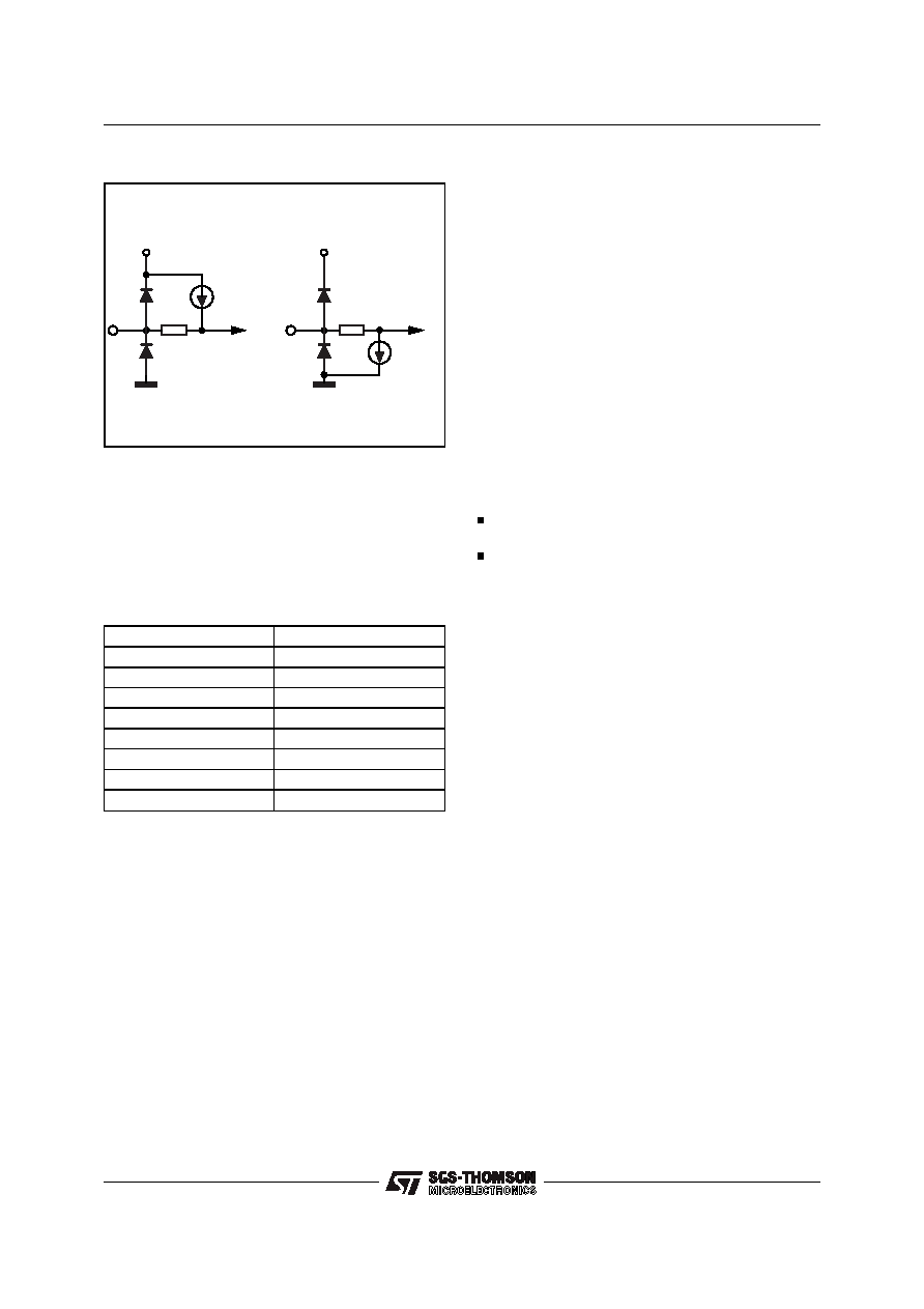
If no connection is made, the pin is either pulled
high or low by internal constant current gener-
ators as shown above.
A listing of the logic and clock inputs is shown in
Table 1 with the corresponding default state.
1.3 Modes of Operation
There are 5 basic modes of operation.
1) Tristate
When Output Enable is low, the output power
drivers are tristated.
2) Start-Up
With Output Enable high, bringing Run/Brake
from a low to a high will energize the motor and
the system will be driven by the Fully-Integrated
StartUp Algorithm.
A user-defined Start-Up Algorithm, under control
of a MicroProcessor, can also be achieved via the
sequence increment input.
3) Run
Run mode is achieved when the motor speed
(controlled
by
the
external
microprocessor)
reaches the nominal speed.
4) Park
When Run/Brake is brought low, energy to park
the heads may be derived from the rectified Bemf.
The energy recovery time is a function of the
Brake Delay Time Constant. In this state, the qui-
escent current of the device is minimized (sleep
mode).
5) Brake
After the Energy Recovery Time-Out, the device
is in Brake, with all lower Drivers in full conduc-
tion.
There are two mutually exclusive conditions
which may be present during the Tristate Mode
(wake up):
a)the spindle is stopped.
b)the system is still running at a speed that
allows for resynchronization.
In order to minimize the ramp up time, the micro-
controller has the possibility to:
check the SPIN SENSE pin, (which toggles at
the Bemf zero crossing frequency)
enable the power to the motor based on the
previous information. Otherwise the
P may is-
sue a Brake command, followed by the start-
up procedure after the motor has stopped spin-
ning.
2.0 STATE DIAGRAMS
2.1 State Diagram
Figure 2-1 is a complete State Diagram of the
controller depicting the operational flow as a func-
tion of the control pins and motor status. The flow
can be separated into four distinct operations.
2.2 Align + Go
Figure 2-2 represent the normal flow that will
achieve a spin-up of the spindle motor using the
internally generated start up algorithm.
Upon
power
up,
or
from
any
state
with
Run/Brake low the controller first sets the state
machine for State=1 with the Outputs Tristated.
The period counter that monitors the time be-
tween zero crossing is stopped, analog with the
phase and mask delay counters.
When Run/Brake is brought high, the motor is in
the first part of the align mode at State 2 (Output
A high and Output C low). If Output Enable is
high, the controller first checks to determine if the
motor is still spinning for a time of 21
(with
Sys_Clk = 10MHz). The drivers are now enabled
and after the align time-out, (64/Falign), the se-
quencer double increments the outputs to State 4
(Output B high and Output A low). The first part
of this align mode is used to reduce the effects of
stiction
Pin Function
Configuration
Tdly (0,1,2)
Pull-Down
Select Pole
Pull-Down
PWM/Linear
Pull-Down
Output Enable
Pull-Down
Run/Brake
Pull-Up
Sequence Increment
Pull-Down
System Clock
Pull-Up
Faling
Pull-Up
Table 1
330
VLOGIC
10
A
330
VLOGIC
10
A
PULL-UP
PULL-DOWN
D95IN279
Figure 1-2
L6238S
9/31
相关PDF资料 |
PDF描述 |
|---|---|
| L6238S013TR | BRUSHLESS DC MOTOR CONTROLLER, 5 A, PQCC44 |
| L6246 | VOICE COIL MOTOR CONTROLLER, 3 A, PQFP44 |
| L6258EA | STEPPER MOTOR CONTROLLER, 2 A, PDSO36 |
| L6268 | VOICE COIL MOTOR CONTROLLER, 2.1 A, PQFP44 |
| L6269 | VOICE COIL MOTOR CONTROLLER, 2.1 A, PQFP44 |
相关代理商/技术参数 |
参数描述 |
|---|---|
| L6239 | 制造商:未知厂家 制造商全称:未知厂家 功能描述: |
| L623C | 制造商:未知厂家 制造商全称:未知厂家 功能描述:THYRISTOR MODULE|BRIDGE|HALF-CNTLD|CA|280V V(RRM)|46A I(T) |
| L623F | 制造商:未知厂家 制造商全称:未知厂家 功能描述:THYRISTOR MODULE|BRIDGE|HALF-CNTLD|CA|280V V(RRM)|46A I(T) |
| L624 | 制造商:CRYDOM 制造商全称:Crydom Inc., 功能描述:Power Modules |
| L6242 | 制造商:STMICROELECTRONICS 制造商全称:STMicroelectronics 功能描述:VOICE COIL MOTOR DRIVER |
发布紧急采购,3分钟左右您将得到回复。