- 您现在的位置:买卖IC网 > PDF目录44530 > LM1572MTCX-ADJ/NOPB (NATIONAL SEMICONDUCTOR CORP) 3.2 A SWITCHING REGULATOR, 570 kHz SWITCHING FREQ-MAX, PDSO16 PDF资料下载
参数资料
| 型号: | LM1572MTCX-ADJ/NOPB |
| 厂商: | NATIONAL SEMICONDUCTOR CORP |
| 元件分类: | 稳压器 |
| 英文描述: | 3.2 A SWITCHING REGULATOR, 570 kHz SWITCHING FREQ-MAX, PDSO16 |
| 封装: | TSSOP-16 |
| 文件页数: | 14/17页 |
| 文件大小: | 583K |
| 代理商: | LM1572MTCX-ADJ/NOPB |
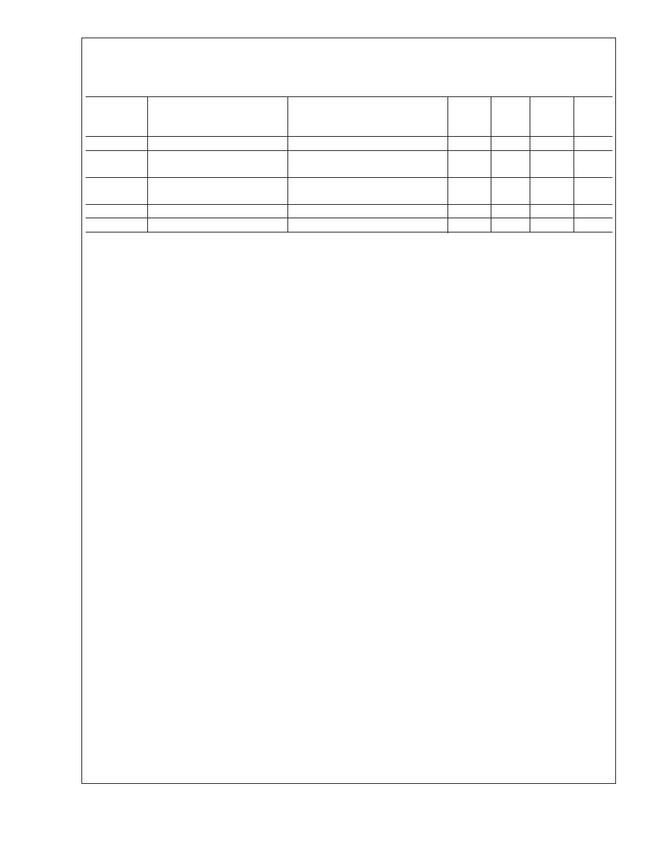
Electrical Characteristics (Continued)
Unless otherwise specified, all limits are guaranteed for T
A = 25C, VIN = 15V, VCOMP = 1.5V, VSD = 5V, ILOAD = 0A, unless
otherwise noted. Boldface apply over the temperature extremes. ’V
FB low (high)’ is 0.95 (1.05) times the nominal value at
regulation.
Symbol
Parameter
Conditions
Min
Typ
Max
Units
I
SS
Softstart Pin Current
V
SS = 1V,VFB=0V
2.5
4.5
8
A
I
SD
Shutdown Supply Current
V
SD = 0V,VCOMP = 1V,VFB low
26
52
75
A
I
STDBY
Standby Supply Current
V
SD = 1.5V, Comp Open
2.3
4
4.3
mA
V
UVLO
Undervoltage Lockout Threshold
Comp Open, V
FB low
2.2
2.38
2.5
V
SD
Shutdown Threshold
Comp Open, V
COMP = 1V, VFB low
0.75
1.0
1.28
V
Note 1: Absolute maximum ratings indicate limits beyond which damage to the device may occur. Operating ratings indicate conditions for which the device is
intended to be functional, but specific performance is not guaranteed. For guaranteed specifications and the test conditions, see the Electrical Characteristics.
Note 2: This is for the human body model, which is a 100pF capacitor discharged through a 1.5k resistor into each pin.
Note 3: Minimum input voltage is defined as the voltage where internal bias lines are still regulated so that the reference voltage and oscillator remain constant.
Actual minimum input voltage to maintain output in regulation depends on output voltage and load current. In particular, the required duty cycle must be less than
the lowest possible upper duty cycle limit of the controller (DMAX = 0.86). The maximum input voltage will also depend on output voltage and load current. In
particular, the required duty cycle must be greater than the lowest possible duty cycle limit of the controller (DMIN = 0.15), estimated from the typical minimum
on-time, which is about 300ns.
Note 4: Junction to Ambient thermal resistance with the TSSOP-16 package soldered on a 1oz. printed circuit board with copper area of approximately 1in2.
Note 5: All limits guaranteed at room temperature (standard face type) and at temperature extremes (bold face type). All room temperature limits are 100%
production tested. All limits at temperature extremes are guaranteed via correlation using Statistical Quality Control (SQC) methods. All limits are used to calculate
Average Outgoing Quality Level (AOQL).
Note 6: Typical numbers are at 25C and represent the most likely norm.
Note 7: Transconductance and voltage gain refer to the internal amplifier, excluding any voltage divider as is present on the fixed voltage parts. To calculate the gain
and transconductance for the fixed voltage parts, divide values shown in table by the ratio VFB_5/2.42 = 2.07 for the 5V part and by VFB_3.3/2.42 = 1.36 for the 3.3V
part.
Note 8: To ensure stable operation, the maximum recommended operating duty cycle is 80%.
LM1572
www.national.com
6
相关PDF资料 |
PDF描述 |
|---|---|
| LM1572MTCX-5.0/NOPB | 3.2 A SWITCHING REGULATOR, 570 kHz SWITCHING FREQ-MAX, PDSO16 |
| LM1572MTCX-3.3/NOPB | 3.2 A SWITCHING REGULATOR, 570 kHz SWITCHING FREQ-MAX, PDSO16 |
| LM1572MTC-3.3/NOPB | 3.2 A SWITCHING REGULATOR, 570 kHz SWITCHING FREQ-MAX, PDSO16 |
| LM1572MTC-ADJ/NOPB | 3.2 A SWITCHING REGULATOR, 570 kHz SWITCHING FREQ-MAX, PDSO16 |
| LM1575J-ADJ/883 | 3 A SWITCHING REGULATOR, 58 kHz SWITCHING FREQ-MAX, CDIP16 |
相关代理商/技术参数 |
参数描述 |
|---|---|
| LM1575 | 制造商:NSC 制造商全称:National Semiconductor 功能描述:SIMPLE SWITCHER㈢ 1A Step-Down Voltage Regulator |
| LM1575_07 | 制造商:NSC 制造商全称:National Semiconductor 功能描述:SIMPLE SWITCHER㈢ 1A Step-Down Voltage Regulator |
| LM1575-12 | 制造商:NSC 制造商全称:National Semiconductor 功能描述:SIMPLE SWITCHER 1A STEP-DOWN VOLTAGE REGULATOR |
| LM1575-15 | 制造商:NSC 制造商全称:National Semiconductor 功能描述:SIMPLE SWITCHER(TM) 1A STEP-DOWN VOLTAGE REGULATOR |
| LM1575-5.0AK | 制造商:未知厂家 制造商全称:未知厂家 功能描述:Voltage-Mode SMPS Controller |
发布紧急采购,3分钟左右您将得到回复。