- 您现在的位置:买卖IC网 > PDF目录44530 > LM1572MTCX-ADJ/NOPB (NATIONAL SEMICONDUCTOR CORP) 3.2 A SWITCHING REGULATOR, 570 kHz SWITCHING FREQ-MAX, PDSO16 PDF资料下载
参数资料
| 型号: | LM1572MTCX-ADJ/NOPB |
| 厂商: | NATIONAL SEMICONDUCTOR CORP |
| 元件分类: | 稳压器 |
| 英文描述: | 3.2 A SWITCHING REGULATOR, 570 kHz SWITCHING FREQ-MAX, PDSO16 |
| 封装: | TSSOP-16 |
| 文件页数: | 7/17页 |
| 文件大小: | 583K |
| 代理商: | LM1572MTCX-ADJ/NOPB |
Application Information (Continued)
The available tolerances should also be checked out as they
govern what can be considered a ’standard’ value for a
certain requirement. Therefore for example, if 1% resistors
are required, it will be almost impossible to find such a
resistor in the E12 or E24 series, for which 10% and 5%
respectively are more commonly available tolerances. E48 is
normally 2%, E96 is 1%, and E192 is 0.5%/ 0.1%. Further,
each series is usually ’devoted’ to its tolerance.Therefore a
value like 221
which exists in E96 and E192 may not be
readily available as a 2% resistor, simply because in E48
(which is usually for 2% resistors), the nearest standard
values are 215
and 226. One could always pay more for
better resistors than required, but the question is one of
’optimum’
design
here.
’Optimum’
means
a
correct
consideration/compromise between several factors: cost,
tolerance of the resistors, and the output error (from all
related sources). All these indicate that the task of correctly
selecting a resistive divider is usually under-estimated or
down-played.
Looking at the standard value series, it should also be noted
that every series is a subset of the next higher series.
However there are two distinct sets. Therefore E6 is a subset
of E12 and E24, and E48 is a subset of E96 and E192.
However no E24 value can be found in E48 (or higher). As
an example, the ’well-known’ resistance value of 220
is
available in E6, E12 and E24. But this value does not exist in
the higher (more modern) series.There the closest ’standard’
values are 215
and 226 in E48, and also 221 in the
more expensive series as discussed above. The following
example will make these considerations clearer.
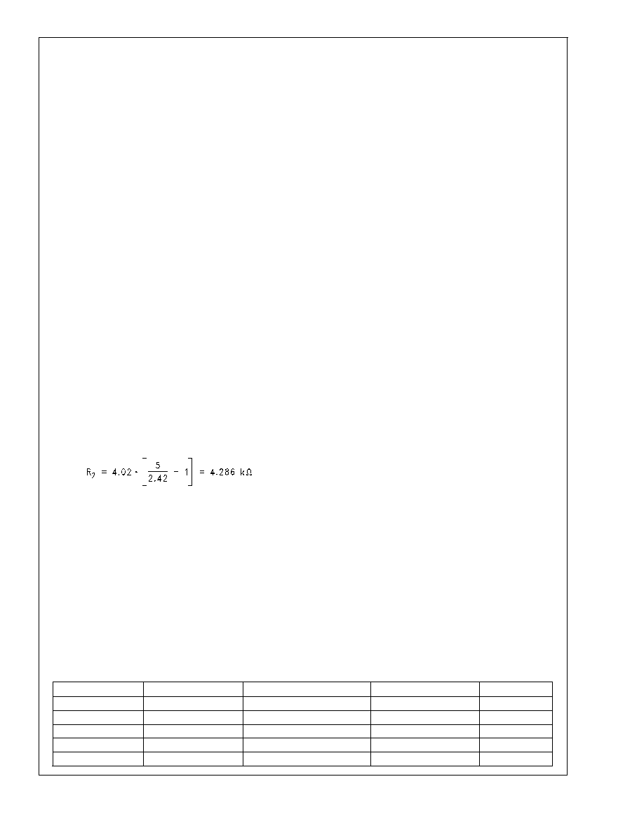
Example: It is required to set an output voltage of 5V using
the adjustable part. R
1 is taken to be a 4.02k (E48 series)
standard resistor value (for a 0.25% error expected on ac-
count of the feedback pin current). So using the basic divider
equation
This is, as expected, not a standard resistance value. The
closest is 4.32k (E96). Using that value for R
2 would give an
additional error of (4.324.286)/4.286 = 0.8% (on top of the
errors due to other causes). If this is unacceptable, an
additional resistor can be placed in parallel with the 4.32k.
Checking to see if a ’standard’ 560k resistor would do the
job: this gives an effective value of (4.32*560)/(4.32 + 560) =
4.287k, which is almost exactly the required value of 4.286k!
More on the choice of the 560k will follow below.
Final recommended values here are
R
1 = 4.02k, and R2 = 4.32k \ 560k
Note that the effect of other tolerances have not been con-
sidered, including the possible spread on V
FB itself (this
adds another +,- 1.25% of error as indicated by the Electrical
Characteristics tables). Another significant source of error to
consider is the tolerance of the resistors themselves. For a
majority of applications these are generally chosen to be of
1% tolerance. But they can be chosen to be 0.5% or 0.1% in
critical applications, or even 2% in less sensitive applica-
tions.
The percentage error in the output voltage is 2*(V
O-VFB)*Tol/
V
O. So for example with 1% resistors being used to set the
output to 5V, the maximum error on the output on account of
the resistor tolerance is 2*(5-2.42)*1/5=1%. (This is actually
+,-1% since the tolerance of the resistors to start with was
also +,-1%). For a 3.3V output, the error is about +,-0.5%
with 1% resistors. Similarly, the output error (on this account)
is reduced by a factor of 10, if 0.1% resistors are used
instead.
As for the shunt resistor of 560k (in parallel to R
2), it is not
really necessary to have a very tight tolerance for this resis-
tor. Since the entire effect of this resistor is to add a slight
’trim’ to the output voltage, the effect of its tolerance on the
output is proportionally small too. The proportionality factor
here is the ratio R
2/560k. Therefore, the 560k can be a 5%
resistor in almost all applications. This was actually kept in
mind well in advance, when the value 560k was initially
proposed. Because 560k happens to be a standard value in
the 5% series (E24), though it does not exist in the higher
(expensive) series. Cost was clearly of concern here.
Concluding this discussion, there is a last observation to
make concerning the fixed voltage part. Here the output is
normally connected to the feedback pin directly. The resis-
tive divider is therefore internal. The relevant design infor-
mation here is that for the 5V part the effective resistance
(R
1 +R2) from feedback pin to ground is 10k. For the 3.3V
part this resistance is 6.6k. This gives a current of 0.5mA
passing through the divider. This is a satisfactory choice,
since it was seen to limit the contribution of the feedback
node current on the output to less than 0.3%. The error due
to the ’tolerance’ of the resistive divider is almost negligible
for fixed voltage parts. To understand this, the reason for the
error from an external divider, as used in an adjustable part,
must first be clarified. There the worst case situation is
where one resistor is at the lower end of its tolerance band,
while at the same time the other resistor is at the upper end
of the tolerance band. This gives the worst case error on the
output. However if both the upper and lower resistors were
simultaneously say ’x%’ higher (or lower) than their nominal,
their ’ratio’ would remain unchanged. It was earlier indicated
that if the ratio of the resistances in a resistive divider is
maintained, then theoretically there is no change in the
output voltage. This is the situation in the case of the internal
resistive divider. Because the two resistors are in the same
package, any drift or tolerance will affect both of them almost
equally. It is expected, and borne out, that their ’relative
tolerance’ is typically almost 10 times better than the (abso-
lute) tolerance of each. Therefore, the effect of the tolerance
of the resistors in an internal resistive divider, as in fixed
voltage parts, can be ignored.
Bill of Material for LM1572 Evaluation Board
Designator
Description
Manufacturer
Part Number
Qty.
U1
LM1572-5.0
National Semiconductor
LM1572-5.0
1
D1
2A/30V Schottky
International Rectifier
20BQ030
1
D2
SS diode
General Semiconductor
1N4448W
1
L1
8.2H
Gowanda
SMP3013-821K*
1
C1
22F/35V
Vishay-Sprague
595D226X0035R2T
1
LM1572
www.national.com
15
相关PDF资料 |
PDF描述 |
|---|---|
| LM1572MTCX-5.0/NOPB | 3.2 A SWITCHING REGULATOR, 570 kHz SWITCHING FREQ-MAX, PDSO16 |
| LM1572MTCX-3.3/NOPB | 3.2 A SWITCHING REGULATOR, 570 kHz SWITCHING FREQ-MAX, PDSO16 |
| LM1572MTC-3.3/NOPB | 3.2 A SWITCHING REGULATOR, 570 kHz SWITCHING FREQ-MAX, PDSO16 |
| LM1572MTC-ADJ/NOPB | 3.2 A SWITCHING REGULATOR, 570 kHz SWITCHING FREQ-MAX, PDSO16 |
| LM1575J-ADJ/883 | 3 A SWITCHING REGULATOR, 58 kHz SWITCHING FREQ-MAX, CDIP16 |
相关代理商/技术参数 |
参数描述 |
|---|---|
| LM1575 | 制造商:NSC 制造商全称:National Semiconductor 功能描述:SIMPLE SWITCHER㈢ 1A Step-Down Voltage Regulator |
| LM1575_07 | 制造商:NSC 制造商全称:National Semiconductor 功能描述:SIMPLE SWITCHER㈢ 1A Step-Down Voltage Regulator |
| LM1575-12 | 制造商:NSC 制造商全称:National Semiconductor 功能描述:SIMPLE SWITCHER 1A STEP-DOWN VOLTAGE REGULATOR |
| LM1575-15 | 制造商:NSC 制造商全称:National Semiconductor 功能描述:SIMPLE SWITCHER(TM) 1A STEP-DOWN VOLTAGE REGULATOR |
| LM1575-5.0AK | 制造商:未知厂家 制造商全称:未知厂家 功能描述:Voltage-Mode SMPS Controller |
发布紧急采购,3分钟左右您将得到回复。