- 您现在的位置:买卖IC网 > PDF目录44549 > LM2590HV3.3MDC (NATIONAL SEMICONDUCTOR CORP) 3 A SWITCHING REGULATOR, 173 kHz SWITCHING FREQ-MAX, UUC PDF资料下载
参数资料
| 型号: | LM2590HV3.3MDC |
| 厂商: | NATIONAL SEMICONDUCTOR CORP |
| 元件分类: | 稳压器 |
| 英文描述: | 3 A SWITCHING REGULATOR, 173 kHz SWITCHING FREQ-MAX, UUC |
| 封装: | DIE |
| 文件页数: | 24/24页 |
| 文件大小: | 816K |
| 代理商: | LM2590HV3.3MDC |
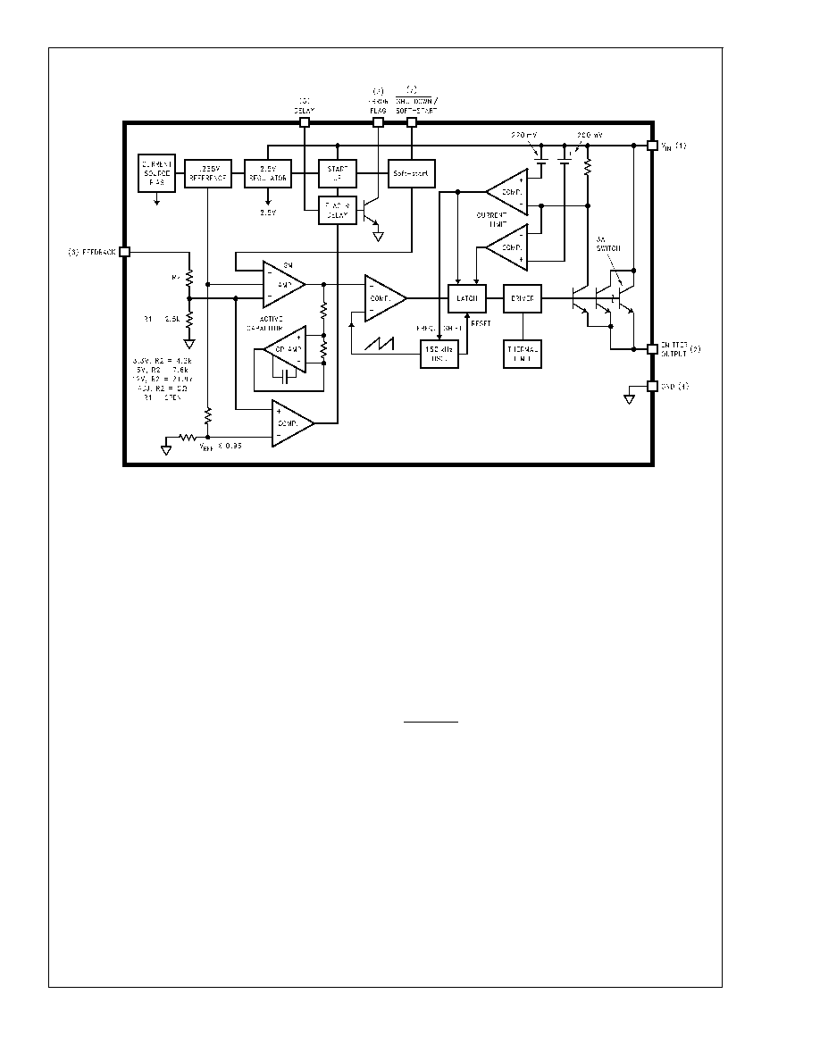
Block Diagram
10134730
PIN FUNCTIONS
+V
IN (Pin 1) — This is the positive input supply for the IC
switching regulator. A suitable input bypass capacitor must
be present at this pin to minimize voltage transients and to
supply the switching currents needed by the regulator.
Output (Pin 2) — Internal switch. The voltage at this pin
switches between approximately (+V
IN VSAT) and approxi-
mately 0.5V, with a duty cycle of V
OUT/VIN.
Error Flag (Pin 3) — Open collector output that goes active
low (
≤ 1.0V) when the output of the switching regulator is out
of regulation (less than 95% of its nominal value). In this
state it can sink maximum 3mA. When not low, it can be
pulled high to signal that the output of the regulator is in
regulation (power good). During power-up, it can be pro-
grammed to go high after a certain delay as set by the Delay
pin (Pin 5). The maximum rating of this pin should not be
exceeded, so if the rail to which it will be pulled-up to is
higher than 45V, a resistive divider must be used instead of
a single pull-up resistor, as indicated in
Ground (Pin 4) — Circuit ground.
Delay (Pin 5) — This sets a programmable power-up delay
from the moment that the output reaches regulation, to the
high signal output (power good) on Pin 3. A capacitor on this
pin starts charging up by means on an internal () 3 A)
current source when the regulated output rises to within 5%
of its nominal value. Pin 3 goes high (with an external
pull-up) when the voltage on the capacitor on Pin 5 exceeds
1.3V. The voltage on this pin is clamped internally to about
1.7V. If the regulated output drops out of regulation (less
than 95% of its nominal value), the capacitor on Pin 5 is
rapidly discharged internally and Pin 3 will be forced low in
about 1/1000
th of the set power-up delay time.
Feedback (Pin 6) — Senses the regulated output voltage to
complete the feedback loop. This pin is directly connected to
the Output for the fixed voltage versions, but is set to 1.23V
by means of a resistive divider from the output for the
Adjustable version. If a feedforward capacitor is used (Ad-
justable version), then a negative voltage spike is generated
on this pin whenever the output is shorted. This happens
because the feedforward capacitor cannot discharge fast
enough, and since one end of it is dragged to Ground, the
other end goes momentarily negative. To prevent the energy
rating of this pin from being exceeded, a small-signal Schot-
tky diode to Ground is recommended for DC input voltages
above 40V whenever a feedforward capacitor is present
(See
Figure 1). Feedforward capacitor values larger than 0.1
F are not recommended for the same reason, whatever be
the DC input voltage.
Shutdown /Soft-start (Pin 7) — The regulator is in shut-
down mode, drawing about 90 A, when this pin is driven to
a low level (
≤ 0.6V), and is in normal operation when this Pin
is left floating (internal-pullup) or driven to a high level (
≥
2.0V). The typical value of the threshold is 1.3V and the pin
is internally clamped to a maximum of about 7V. If it is driven
higher than the clamp voltage, it must be ensured by means
of an external resistor that the current into the pin does not
exceed 1mA. The duty cycle is minimum (0%) if this Pin is
below 1.8V, and increases as the voltage on the pin is
increased. The maximum duty cycle (100%) occurs when
this pin is at 2.8V or higher. So adding a capacitor to this pin
produces a softstart feature. An internal current source will
charge the capacitor from zero to its internally clamped
value. The charging current is about 5 A when the pin is
below 1.3V but is reduced to only 1.6 A above 1.3V, so as
to allow the use of smaller softstart capacitors.
LM2590HV
www.national.com
9
相关PDF资料 |
PDF描述 |
|---|---|
| LM2594-12MDC | 1.4 A SWITCHING REGULATOR, 173 kHz SWITCHING FREQ-MAX, UUC |
| LM2594-5.0MWC | 1.4 A SWITCHING REGULATOR, 173 kHz SWITCHING FREQ-MAX, UUC |
| LM2594-ADJMDC | 1.4 A SWITCHING REGULATOR, 173 kHz SWITCHING FREQ-MAX, UUC |
| LM2594-ADJMWC | 1.4 A SWITCHING REGULATOR, 173 kHz SWITCHING FREQ-MAX, UUC |
| LM2594HV-12MWC | 1.4 A SWITCHING REGULATOR, 173 kHz SWITCHING FREQ-MAX, UUC |
相关代理商/技术参数 |
参数描述 |
|---|---|
| LM2590HVS-3.3 | 功能描述:直流/直流开关转换器 RoHS:否 制造商:STMicroelectronics 最大输入电压:4.5 V 开关频率:1.5 MHz 输出电压:4.6 V 输出电流:250 mA 输出端数量:2 最大工作温度:+ 85 C 安装风格:SMD/SMT |
| LM2590HVS-3.3/NOPB | 功能描述:直流/直流开关转换器 RoHS:否 制造商:STMicroelectronics 最大输入电压:4.5 V 开关频率:1.5 MHz 输出电压:4.6 V 输出电流:250 mA 输出端数量:2 最大工作温度:+ 85 C 安装风格:SMD/SMT |
| LM2590HVS-5.0 | 功能描述:直流/直流开关转换器 RoHS:否 制造商:STMicroelectronics 最大输入电压:4.5 V 开关频率:1.5 MHz 输出电压:4.6 V 输出电流:250 mA 输出端数量:2 最大工作温度:+ 85 C 安装风格:SMD/SMT |
| LM2590HVS5.0/NOPB | 制造商:Texas Instruments 功能描述: |
| LM2590HVS-5.0/NOPB | 功能描述:直流/直流开关转换器 RoHS:否 制造商:STMicroelectronics 最大输入电压:4.5 V 开关频率:1.5 MHz 输出电压:4.6 V 输出电流:250 mA 输出端数量:2 最大工作温度:+ 85 C 安装风格:SMD/SMT |
发布紧急采购,3分钟左右您将得到回复。