- 您现在的位置:买卖IC网 > PDF目录44549 > LM2590HV3.3MDC (NATIONAL SEMICONDUCTOR CORP) 3 A SWITCHING REGULATOR, 173 kHz SWITCHING FREQ-MAX, UUC PDF资料下载
参数资料
| 型号: | LM2590HV3.3MDC |
| 厂商: | NATIONAL SEMICONDUCTOR CORP |
| 元件分类: | 稳压器 |
| 英文描述: | 3 A SWITCHING REGULATOR, 173 kHz SWITCHING FREQ-MAX, UUC |
| 封装: | DIE |
| 文件页数: | 6/24页 |
| 文件大小: | 816K |
| 代理商: | LM2590HV3.3MDC |
Application Information
INDUCTOR SELECTION PROCEDURE
Application Note AN-1197 titled ’Selecting Inductors for Buck
Converters’ provides detailed information on this topic. For a
quick-start the designer may refer to the nomographs pro-
vided in
Designer to a more general selection of available inductors,
the nomographs provide the required inductance and also
the energy in the core expressed in microjoules (J), as an
alternative to just prescribing custom parts. The following
points need to be highlighted:
1.
The Energy values shown on the nomographs apply to
steady operation at the corresponding x-coordinate
(rated maximum load current). However under start-up,
without soft-start, or a short-circuit on the output, the
current in the inductor will momentarily/repetitively hit
the current limit I
CLIM of the device, and this current
could be much higher than the rated load, I
LOAD. This
represents an overload situation, and can cause the
Inductor to saturate (if it has been designed only to
handle the energy of steady operation). However most
types of core structures used for such applications have
a large inherent air gap (for example powdered iron
types or ferrite rod inductors), and so the inductance
does not fall off too sharply under an overload. The
device is usually able to protect itself by not allowing the
current to ever exceed I
CLIM. But if the DC input voltage
to the regulator is over 40V, the current can slew up so
fast under core saturation, that the device may not be
able to act fast enough to restrict the current. The cur-
rent can then rise without limit till destruction of the
device takes place.
Therefore to ensure reliability, it is
recommended, that if the DC Input Voltage exceeds
40V, the inductor must ALWAYS be sized to handle an
instantaneous current equal to ICLIM without saturating,
irrespective of the type of core structure/material.
2.
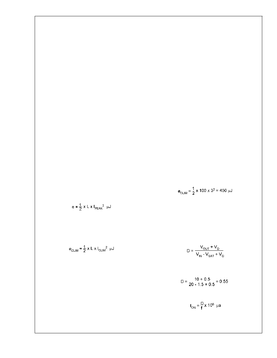
The Energy under steady operation is
where L is in H and I
PEAK is the peak of the inductor current
waveform with the regulator delivering I
LOAD. These are the
energy values shown in the nomographs. See
Example 1
below.
3.
The Energy under overload is
If V
IN > 40V, the inductor should be sized to handle eCLIM
instead of the steady energy values. The worst case I
CLIM for
the LM2590HV is 3A. The Energy rating depends on the
Inductance. See
Example 2 below.
4.
The nomographs were generated by allowing a greater
amount of percentage current ripple in the Inductor as
the maximum rated load decreases (see
Figure 7). This
was done to permit the use of smaller inductors at light
loads.
Figure 7 however shows only the ’median’ value
of the current ripple. In reality there may be a great
spread around this because the nomographs approxi-
mate the exact calculated inductance to standard avail-
able values. It is a good idea to refer to AN-1197 for
detailed calculations if a certain maximum inductor cur-
rent ripple is required for various possible reasons. Also
consider the rather wide tolerance on the nominal induc-
tance of commercial inductors.
5.
Figure 6 shows the inductor selection curves for the
Adjustable version. The y-axis is ’Et’, in Vsecs. It is the
applied volts across the inductor during the ON time of
the switch (V
IN-VSAT-VOUT) multiplied by the time for
which the switch is on in secs. See Example 3 below.
Example 1: (V
IN ≤ 40V) LM2590HV-5.0, VIN = 24V, Output
5V @ 0.8A
1. A first pass inductor selection is based upon
Inductance
and rated max load current. We choose an inductor with the
Inductance value indicated by the nomograph (
Figure 5) and
a current rating equal to the maximum load current. We
therefore quick-select a 100H/0.8 A inductor (designed for
150 kHz operation) for this application.
2. We should confirm that it is rated to handle 50 J (see
Figure 5) by either estimating the peak current or by a
detailed calculation as shown in AN-1197, and also that the
losses are acceptable.
Example 2: (V
IN > 40V) LM2590HV-5.0, VIN = 48V, Output
5V @ 1A
1. A first pass inductor selection is based upon
Inductance
and the switch currrent limit. We choose an inductor with the
Inductance value indicated by the nomograph (
Figure 5) and
a current rating equal to I
CLIM. We therefore quick-select a
100H/3A inductor (designed for 150 kHz operation) for this
application.
2. We should confirm that it is rated to handle e
CLIM by the
procedure shown in AN-1197 and that the losses are accept-
able. Here e
CLIM is:
Example 3: (V
IN ≤ 40V) LM2590HV-ADJ, VIN = 20V, Output
10V @ 1A
1. Since input voltage is less than 40V, a first pass inductor
selection is based upon Inductance and rated max load
current. We choose an inductor with the Inductance value
indicated by the nomograph
Figure 6 and a current rating
equal to the maximum load. But we first need to calculate Et
for the given application. The Duty cycle is
where V
D is the drop across the Catch Diode (
) 0.5V for a
Schottky) and V
SAT the drop across the switch (
)1.5V). So
And the switch ON time is
where f is the switching frequency in Hz. So
LM2590HV
www.national.com
14
相关PDF资料 |
PDF描述 |
|---|---|
| LM2594-12MDC | 1.4 A SWITCHING REGULATOR, 173 kHz SWITCHING FREQ-MAX, UUC |
| LM2594-5.0MWC | 1.4 A SWITCHING REGULATOR, 173 kHz SWITCHING FREQ-MAX, UUC |
| LM2594-ADJMDC | 1.4 A SWITCHING REGULATOR, 173 kHz SWITCHING FREQ-MAX, UUC |
| LM2594-ADJMWC | 1.4 A SWITCHING REGULATOR, 173 kHz SWITCHING FREQ-MAX, UUC |
| LM2594HV-12MWC | 1.4 A SWITCHING REGULATOR, 173 kHz SWITCHING FREQ-MAX, UUC |
相关代理商/技术参数 |
参数描述 |
|---|---|
| LM2590HVS-3.3 | 功能描述:直流/直流开关转换器 RoHS:否 制造商:STMicroelectronics 最大输入电压:4.5 V 开关频率:1.5 MHz 输出电压:4.6 V 输出电流:250 mA 输出端数量:2 最大工作温度:+ 85 C 安装风格:SMD/SMT |
| LM2590HVS-3.3/NOPB | 功能描述:直流/直流开关转换器 RoHS:否 制造商:STMicroelectronics 最大输入电压:4.5 V 开关频率:1.5 MHz 输出电压:4.6 V 输出电流:250 mA 输出端数量:2 最大工作温度:+ 85 C 安装风格:SMD/SMT |
| LM2590HVS-5.0 | 功能描述:直流/直流开关转换器 RoHS:否 制造商:STMicroelectronics 最大输入电压:4.5 V 开关频率:1.5 MHz 输出电压:4.6 V 输出电流:250 mA 输出端数量:2 最大工作温度:+ 85 C 安装风格:SMD/SMT |
| LM2590HVS5.0/NOPB | 制造商:Texas Instruments 功能描述: |
| LM2590HVS-5.0/NOPB | 功能描述:直流/直流开关转换器 RoHS:否 制造商:STMicroelectronics 最大输入电压:4.5 V 开关频率:1.5 MHz 输出电压:4.6 V 输出电流:250 mA 输出端数量:2 最大工作温度:+ 85 C 安装风格:SMD/SMT |
发布紧急采购,3分钟左右您将得到回复。