- 您现在的位置:买卖IC网 > PDF目录44549 > LM2637M/NOPB (NATIONAL SEMICONDUCTOR CORP) SWITCHING CONTROLLER, 1000 kHz SWITCHING FREQ-MAX, PDSO24 PDF资料下载
参数资料
| 型号: | LM2637M/NOPB |
| 厂商: | NATIONAL SEMICONDUCTOR CORP |
| 元件分类: | 稳压器 |
| 英文描述: | SWITCHING CONTROLLER, 1000 kHz SWITCHING FREQ-MAX, PDSO24 |
| 封装: | SOIC-24 |
| 文件页数: | 3/17页 |
| 文件大小: | 803K |
| 代理商: | LM2637M/NOPB |
Applications Information (Continued)
Notice however, that the r
DS_ON of the FET has a positive
temperature coefficient and it can increase by as much as
50% when heated up. Also the distribution of the r
DS_ON can
be fairly wide, a 1.25 to 1.5 ratio is not uncommon. Consult
the MOSFET vendor for further information on the distribu-
tion of r
DS_ON.
The designer should carefully choose the value of R
IMAX so
that even under the extreme case (largest r
DS_ON and high-
est temperature) the current limit will not trigger below the
preset value.
To provide the greatest protection over the high-side FET,
cycle-by-cycle protection is implemented. The sampling of
the V
DS starts as early as 250 ns after the FET is turned on.
Whenever an over-current condition is detected, the high-
side FET is immediately turned off and the low-side FET
turned on. This status remains for the rest of the cycle. The
same procedure applies to the next switching cycle. The
blanking time of 250 ns is to avoid the switching noise that
occurs whenever the FET is turned on.
The resistor between CS pin and the switching node
(source of the high-side FET) is important for minimizing the
noise and negative voltage present at the CS pin. A resis-
tance of 100
to 300 is recommended.
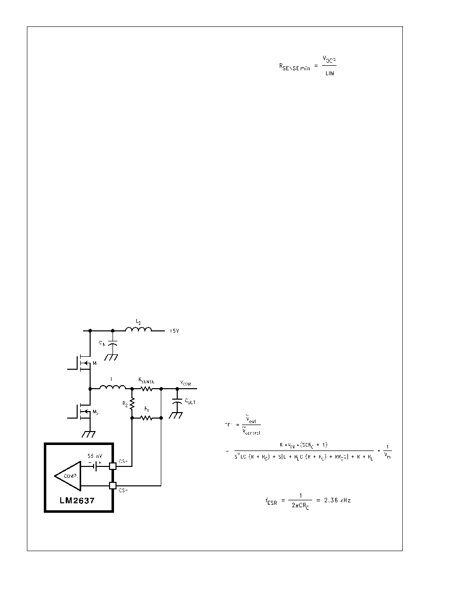
Method 2 — Current Sense Resistor
This method uses a sense resistor in series with the output
inductor to detect the load current. SeeFigure 5. The voltage
across the sense resistor is proportional to load current. In
the case that the sense resistor is of discrete type (i.e., not a
PCB etch resistor) or the sense resistor value is optimized
for dynamic voltage positioning (see the Dynamic Position-
ing of Load Voltage section), it may be necessary to use two
signal level resistors, R
1 and R2 to appropriately set the
desired current limit.
For a given current limit value, the minimum R
SENSE is
determined by:
(4)
where V
OCP is the over-current trip voltage and is typically
55 mV, see the Electrical Characteristic table. For example,
for a 20A current limit, the minimum R
SENSE is 2.75 m
.Ifa
3m
sense resistor is used instead, use appropriate values
of R
1 and R2 to make the voltage across R1 to be VOCP when
the voltage across R
SENSE is 60 mV.
The discrete current sense resistor usually has a very good
temperature coefficient and tolerance. A temperature coeffi-
cient of ±30 ppm/C is typical. Tolerance is usually ±1% or
±5%. Vishay Dale and IRC offer a broad range of discrete
sense resistors.
A PCB etch resistor can also be used as the R
SENSE. The
advantage of that approach is flexible resistance, which will
result in minimum power loss. R
1 and R2 may also be
eliminated. The drawback is too high a temperature coeffi-
cient, typically +4000 ppm/C, which will result in a much less
accurate current limit than a discrete sense resistor. The
copper thickness of a PCB is usually of 5% tolerance.
Linear Section — There is no current limit function in the
linear controllers. However, if there is ever a severe over-
load, the output voltage may drop below 0.63V, in which
case the under-voltage latch-off will provide the protection.
DESIGN CONSIDERATIONS
Control Loop Compensation
Switching Section — A switching regulator should be prop-
erly compensated to achieve a stable operation, tight regu-
lation and good dynamic performance. For a synchronous
buck regulator that needs to meet stringent load transient
requirement such as that of processor core voltage supply, a
2-pole-1-zero compensation network should suffice, such as
the one shown in Figure 6 (C
1,C2,R1 and R2). This is
because the ESR zero of the typical output capacitors is low
enough to make the control-to-output transfer function a
single-pole roll-off.
As an example, let us figure out the values of the compen-
sation network components in Figure 6. Assume the follow-
ing parameters:R=20
,R
L =20m
,R
C =9m
,L =2H,
C = 7.5 mF, V
IN =5V, Vm = 2V and PWM frequency = 300
kHz. Notice R
L is the sum of the inductor DC resistance and
the on resistance of the FET’s.
The control-to-output transfer function is:
(5)
The ESR zero frequency is:
(6)
The double pole frequency is:
10084809
FIGURE 5. Current Limit via Current Sense Resistor
LM2637
www.national.com
11
相关PDF资料 |
PDF描述 |
|---|---|
| LM2637MWC | SWITCHING CONTROLLER, 1000 kHz SWITCHING FREQ-MAX, UUC |
| LM2639MX/NOPB | SWITCHING CONTROLLER, 8700 kHz SWITCHING FREQ-MAX, PDSO24 |
| LM2639M/NOPB | SWITCHING CONTROLLER, 8700 kHz SWITCHING FREQ-MAX, PDSO24 |
| LM2639MWC | SWITCHING CONTROLLER, 8700 kHz SWITCHING FREQ-MAX, UUC |
| LM2641-ADJMDC | DUAL SWITCHING CONTROLLER, 345 kHz SWITCHING FREQ-MAX, UUC |
相关代理商/技术参数 |
参数描述 |
|---|---|
| LM2637MX/NOPB | 功能描述:IC MOTHERBRD PWR SUPPLY 24-SOIC RoHS:是 类别:集成电路 (IC) >> PMIC - 电源管理 - 专用 系列:- 应用说明:Ultrasound Imaging Systems Application Note 产品培训模块:Lead (SnPb) Finish for COTS Obsolescence Mitigation Program 标准包装:37 系列:- 应用:医疗用超声波成像,声纳 电流 - 电源:- 电源电压:2.37 V ~ 6 V 工作温度:0°C ~ 70°C 安装类型:表面贴装 封装/外壳:56-WFQFN 裸露焊盘 供应商设备封装:56-TQFN-EP(8x8) 包装:管件 |
| LM2638 | 制造商:未知厂家 制造商全称:未知厂家 功能描述: |
| LM2638M | 制造商:Texas Instruments 功能描述: |
| LM2638M/NOPB | 功能描述:IC MOTHERBRD PWR SUPPLY 24-SOIC RoHS:是 类别:集成电路 (IC) >> PMIC - 电源管理 - 专用 系列:- 应用说明:Ultrasound Imaging Systems Application Note 产品培训模块:Lead (SnPb) Finish for COTS Obsolescence Mitigation Program 标准包装:37 系列:- 应用:医疗用超声波成像,声纳 电流 - 电源:- 电源电压:2.37 V ~ 6 V 工作温度:0°C ~ 70°C 安装类型:表面贴装 封装/外壳:56-WFQFN 裸露焊盘 供应商设备封装:56-TQFN-EP(8x8) 包装:管件 |
| LM2638MX | 功能描述:IC MOTHERBRD PWR SUPPLY 24-SOIC RoHS:是 类别:集成电路 (IC) >> PMIC - 电源管理 - 专用 系列:- 应用说明:Ultrasound Imaging Systems Application Note 产品培训模块:Lead (SnPb) Finish for COTS Obsolescence Mitigation Program 标准包装:37 系列:- 应用:医疗用超声波成像,声纳 电流 - 电源:- 电源电压:2.37 V ~ 6 V 工作温度:0°C ~ 70°C 安装类型:表面贴装 封装/外壳:56-WFQFN 裸露焊盘 供应商设备封装:56-TQFN-EP(8x8) 包装:管件 |
发布紧急采购,3分钟左右您将得到回复。