- 您现在的位置:买卖IC网 > PDF目录32307 > LM8500IMT9/NOPB (NATIONAL SEMICONDUCTOR CORP) SPECIALTY CONSUMER CIRCUIT, PDSO48 PDF资料下载
参数资料
| 型号: | LM8500IMT9/NOPB |
| 厂商: | NATIONAL SEMICONDUCTOR CORP |
| 元件分类: | 消费家电 |
| 英文描述: | SPECIALTY CONSUMER CIRCUIT, PDSO48 |
| 封装: | TSSOP-48 |
| 文件页数: | 5/20页 |
| 文件大小: | 327K |
| 代理商: | LM8500IMT9/NOPB |
10.0 Oscillator (Continued)
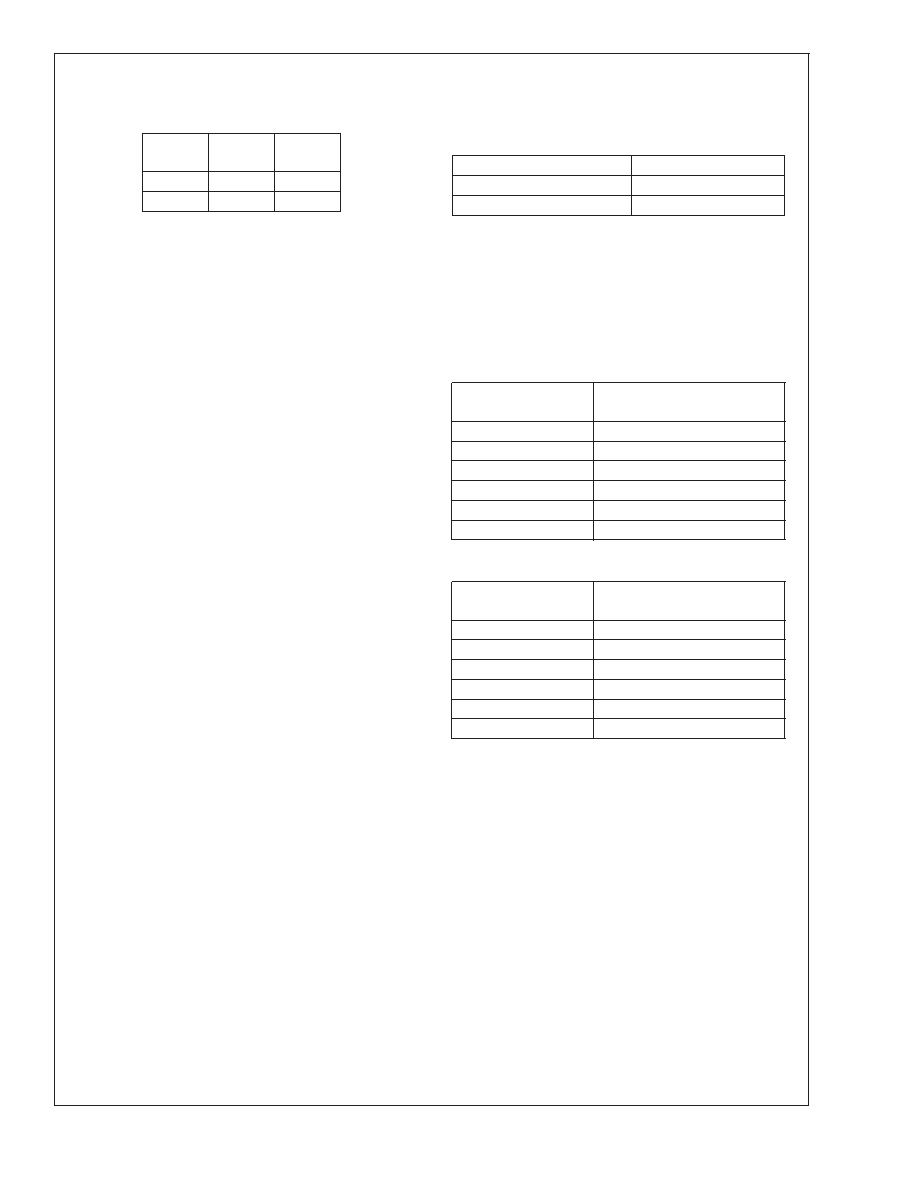
TABLE 1. Crystal Oscillator Configuration,
T
A = 25C, VCC =5V
C1 (pF)
C2 (pF)
CKI Freq.
(MHz)
18
10
18–36
3.27
The crystal and other oscillator components should be
placed in close proximity to the OSC_IN and OSC_OUT pins
to minimize printed circuit trace length.
The values for the external capacitors should be chosen to
obtain the manufacturer’s specified load capacitance for the
crystal when combined with the parasitic capacitance of the
trace, socket, and package (which can vary from 0 to 8 pF).
The guideline in choosing these capacitors is:
Manufacturer’s specified load cap = (C
1 *C2)/(C1 +C2)+
C
parasitic
C
2 can be trimmed to obtain the desired frequency. C2
should be less than or equal to C
1.
11.0 Power Save Mode (Low Power
Stand-by)
The power consumption of the controller can be minimized
by enabling the low power stand by mode. The power save
mode can be controlled internally by sending a command of
$A2 to the controller, externally by pulling the SHUTDOWN
pin low, or by issuing a driver shutdown command of $A8.
The self power down mode is enabled/disabled by sending a
command of $A2 to the controller. When enabled, the con-
troller automatically goes into low power stand by if no more
touch activity is detected or if there is no UART communica-
tion. The controller automatically comes out of low power
stand by mode when a touch is detected on the touch panel
or if an incoming communication on the UART is detected. In
the low power stand by mode, all activity is disabled, includ-
ing the oscillator. Also, the LED pin is driven high. To wake
up the controller on the UART, the wake up command byte
must be sent, followed by a minimum time delay of 1ms for
the LM8500 and 3ms for the LM8300 before sending any
command byte. The delay time is needed to allow the oscil-
lator to restart and stabilize. Table 2. Startup Times shows
the average startup time for a given operating frequency.
The SHUTDOWN pin will shut down the controller when
pulled low. When the SHUTDOWN pin is pulled low, the
controller will continue to be in the low power stand by mode
until the pin is pulled high or released. While the SHUT-
DOWN pin is pulled low, all activities are stopped and any
touch or communication will be ignored. Immediately follow-
ing the SHUTDOWN pin being released or pulled high, the
controller clears the UART transmit and receive buffers and
resumes normal operation.
The controller can be put in the low power stand by mode by
sending a $A8 command to it. Upon receiving this command,
the controller goes into low power stand by mode. If the self
power down mode is enabled and the controller is put into
low power stand by mode, the controller will wake up if the
wake up command ($A7) is received or if a touch is detected
on the touch panel. If the self power down mode is disabled
and the controller is put into low power stand by mode, the
controller can only be woken up if it receives the wakeup
command. After the controller wakes up, the UART transmit
and receive buffers are cleared and resume normal opera-
tion.
TABLE 2. Startup Times
CKI Frequency
Startup Time
10 MHz
1–10 ms
3.33 MHz
3–10 ms
12.0 Averaging Algorithm
To achieve better accuracy and noise filtering, each X, Y, and
Z coordinate is oversampled by specific amount. The pos-
sible oversampling settings are 1, 2, 4, 8, 16, and 32. The
factory setting is 8. The greater the oversampling, the
greater the accuracy, but the lower the CPPS.
Samples per coordinate vs. CPPS for LM8300
Samples
per coordinate
Coordinate pairs
per second (CPPS)
1
250
2
220
4
190
8
150
16
100
32
65
Samples per coordinate vs. CPPS for LM8500
Samples
per coordinate
Coordinate pairs
per second (CPPS)
1
500
2
430
4
360
8
270
16
190
32
110
12.1 DELTA ALGORITHM
The delta filter is used to remove large variations in sampled
values due to noise and glitches. The delta filter tries to
predict where the next coordinate could be. This is done by
taking the two previous coordinates and subtracting one
from the other, producing a delta value. This delta value is
then added or subtracted to the last coordinate. The result-
ing value is the predicted coordinate. If the new sampled
coordinate is close to this predicted value, then the new
value is accepted as valid and is passed to the focus algo-
rithm, provided the focus algorithm is enabled. If the new
sampled coordinate is not close to the predicted coordinate,
then the value is discarded and is stored to be used in the
following delta calculations.
The number by which the new sampled coordinate can differ
from the predicted coordinate is controlled by setting the Set
Max Delta value. The Set Max Delta value can be from a
value of 0-63. The factory default is 8.
LM8300/LM8500
www.national.com
13
相关PDF资料 |
PDF描述 |
|---|---|
| LM8500HLQ9/NOPB | SPECIALTY CONSUMER CIRCUIT, QCC44 |
| LM8300HVA9/NOPB | SPECIALTY CONSUMER CIRCUIT, PQCC44 |
| LM8300IMT9/NOPB | SPECIALTY CONSUMER CIRCUIT, PDSO48 |
| LM8300HLQ9/NOPB | SPECIALTY CONSUMER CIRCUIT, QCC44 |
| LMF501T-2 | AM, AUDIO SINGLE CHIP RECEIVER, PBCY3 |
相关代理商/技术参数 |
参数描述 |
|---|---|
| LM8500IVA9 | 制造商:NSC 制造商全称:National Semiconductor 功能描述:Four Wire Resistive Touchscreen Controller with Brownout |
| LM8500-REF-01 | 功能描述:显示开发工具 LM8500 DEV KIT RoHS:否 制造商:4D Systems 产品:4Display Shields 工具用于评估:?OLED-160-G1, ?OLED-160-G2 接口类型:Serial 工作电源电压:5 V |
| LM8502 | 制造商:TI 制造商全称:Texas Instruments 功能描述:Intelligent Lighting Management Unit That Fuses a 1.2A Dual High-Side Flash LED Driver with a 10-Output Low-Side LED Driver |
| LM8502TME | 制造商:TI 制造商全称:Texas Instruments 功能描述:Intelligent Lighting Management Unit That Fuses a 1.2A Dual High-Side Flash LED Driver with a 10-Output Low-Side LED Driver |
| LM8502TME/NOPB | 功能描述:LED照明驱动器 RoHS:否 制造商:STMicroelectronics 输入电压:11.5 V to 23 V 工作频率: 最大电源电流:1.7 mA 输出电流: 最大工作温度: 安装风格:SMD/SMT 封装 / 箱体:SO-16N |
发布紧急采购,3分钟左右您将得到回复。