- 您现在的位置:买卖IC网 > PDF目录44976 > LSN-T/16-W3H-C (MURATA POWER SOLUTIONS INC) 1-OUTPUT DC-DC REG PWR SUPPLY MODULE PDF资料下载
参数资料
| 型号: | LSN-T/16-W3H-C |
| 厂商: | MURATA POWER SOLUTIONS INC |
| 元件分类: | 电源模块 |
| 英文描述: | 1-OUTPUT DC-DC REG PWR SUPPLY MODULE |
| 封装: | ROHS COMPLIANT, SIP-11/10 |
| 文件页数: | 4/8页 |
| 文件大小: | 215K |
| 代理商: | LSN-T/16-W3H-C |
Input Fusing
Most applications and or safety agencies require the installation of fuses at the
inputs of power conversion components. The LSN W3 Series are not inter-
nally fused. Therefore, if input fusing is mandatory, either a normal-blow or a
fast-blow fuse with a value no greater than twice the maximum input current
should be installed within the ungrounded input path to the converter.
As a rule of thumb however, we recommend to use a normal-blow or
fast-blow fuse with a typical value of about twice the maximum input current,
calculated at low line with the converter’s minimum efciency.
Safety Considerations
LSN W3 SMT’s are non-isolated DC/DC converters. In general, all DC/DC’s must
be installed, including considerations for I/O voltages and spacing/separation
requirements, in compliance with relevant safety-agency specications (usually
UL/IEC/EN60950-1).
In particular, for a non-isolated converter’s output voltage to meet SELV
(safety extra low voltage) requirements, its input must be SELV compliant. If the
output needs to be ELV (extra low voltage), the input must be ELV.
Input Overvoltage and Reverse-Polarity Protection
LSN W3 SMT Series DC/DC’s do not incorporate either input overvoltage
or input reverse-polarity protection. Input voltages in excess of the speci-
ed absolute maximum ratings and input polarity reversals of longer than
“instantaneous” duration can cause permanent damage to these devices.
Start-Up Time
The VIN to VOUT Start-Up Time is the interval between the time at which a ramp-
ing input voltage crosses the lower limit of the specied input voltage range
and the fully loaded output voltage enters and remains within its specied
accuracy band. Actual measured times will vary with input source impedance,
external input capacitance, and the slew rate and nal value of the input volt-
age as it appears to the converter.
The On/Off to VOUT Start-Up Time assumes the converter is turned off via the
On/Off Control with the nominal input voltage already applied to the converter.
The specication denes the interval between the time at which the converter
is turned on and the fully loaded output voltage enters and remains within its
specied accuracy band. See Typical Performance Curves.
Remote Sense
LSN W3 SMT Series DC/DC converters offer an output sense function on pin 3.
The sense function enables point-of-use regulation for overcoming moderate
IR drops in conductors and/or cabling. Since these are non-isolated devices
whose inputs and outputs usually share the same ground plane, sense is
provided only for the +Output.
The remote sense line is part of the feedback control loop regulating the
DC/DC converter’s output. The sense line carries very little current and conse-
quently requires a minimal cross-sectional-area conductor. As such, it is not
a low-impedance point and must be treated with care in layout and cabling.
Sense lines should be run adjacent to signals (preferably ground), and in cable
and/or discrete-wiring applications, twisted-pair or similar techniques should
be used. To prevent high frequency voltage differences between VOUT and
Sense, we recommend installation of a 1000pF capacitor close to the converter.
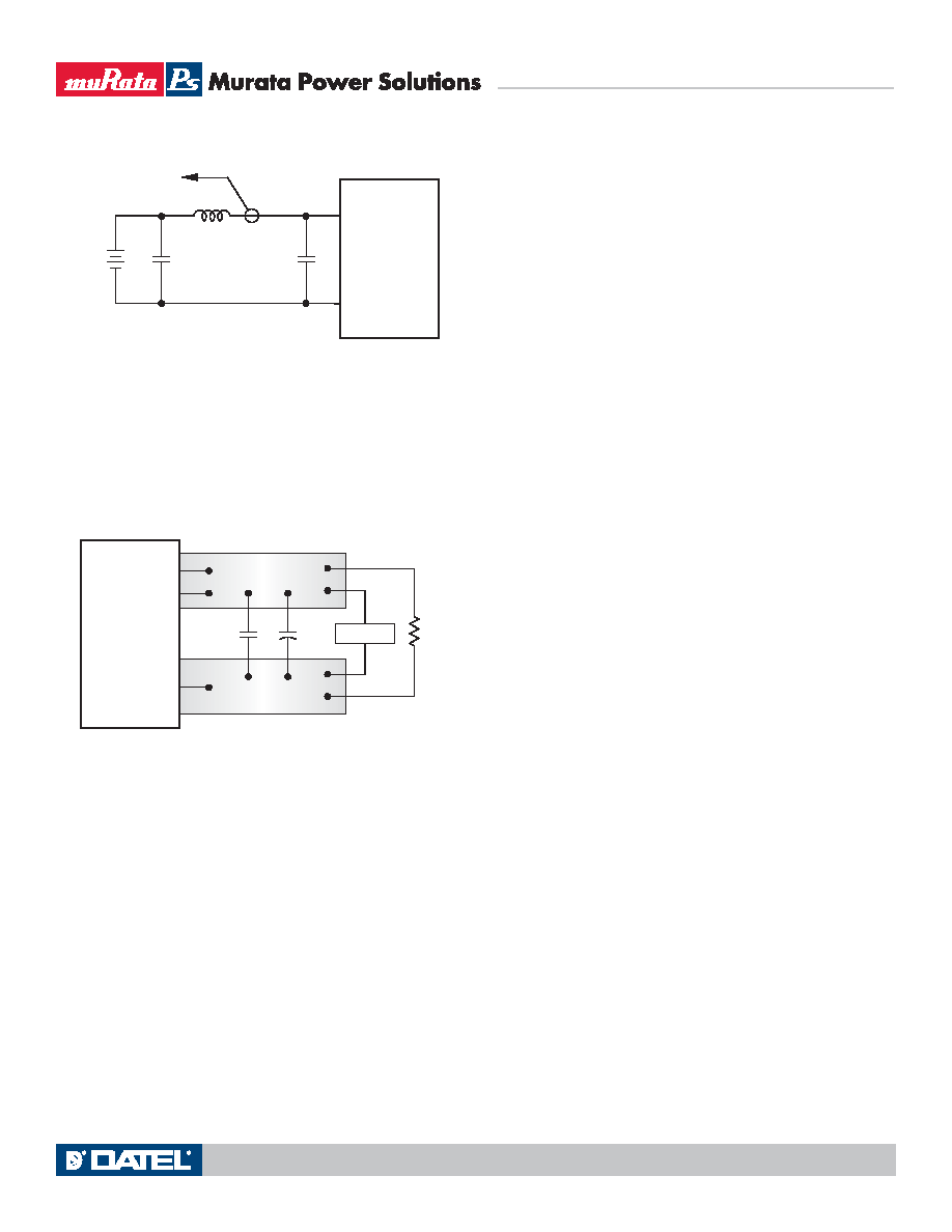
Figure 2. Measuring Input Ripple Current
Output ripple/noise (also referred to as periodic and random deviations or
PARD) may be reduced below specied limits with the installation of additional
external output capacitors. Output capacitors function as true lter elements
and should be selected for bulk capacitance, low ESR, and appropriate fre-
quency response. Any scope measurements of PARD should be made directly
at the DC/DC output pins with scope probe ground less than 0.5" in length
C1
C1 = NA
C2 = 22μF TANTALUM
LOAD 2-3 INCHES (51-76mm) FROM MODULE
C2
RLOAD
COPPER STRIP
SCOPE
+OUTPUT
COMMON
+SENSE
Figure 3. Measuring Output Ripple/Noise (PARD)
All external capacitors should have appropriate voltage ratings and be
located as close to the converters as possible. Temperature variations for all
relevant parameters should be taken into consideration.
You should add only enough output capacitance to attenuate the noise to
your desired level. Large amounts of output capacitance cause poor dynamic
response (step load changes, etc.). Too great an output capacitor can make the
converter oscillate (actually increasing the noise!) while substantial capaci-
tance which is less than the oscillation threshold can still cause ringing and
overshoot. Finally, you must use less output capacitance if the cap is a low
ESR type (OSCON, etc.).
The most effective combination of external I/O capacitors will be a func-
tion of your line voltage and source impedance, as well as your particular load
and layout conditions. Our Applications Engineers can recommend potential
solutions and discuss the possibility of our modifying a given device’s internal
ltering to meet your specic requirements. Contact our Applications Engineer-
ing Group for additional details.
CIN
VIN
CBUS
LBUS
CIN = 2 x 100μF, ESR < 700m
@ 100kHz
CBUS = 1000μF, ESR < 100m
@ 100kHz
LBUS = 1μH
+INPUT
COMMON
CURRENT
PROBE
TO
OSCILLOSCOPE
+
–
Single Output LSN-W3 Models
Non-Isolated, 3-5.5VIN, 0.75-3.3VOUT
16 Amp DC/DC Converters
www.murata-ps.com
email: sales@murata-ps.com
10 Dec 2009
MDC_LSN W3 Models.A02 Page 4 of 8
相关PDF资料 |
PDF描述 |
|---|---|
| LSN2-T/22-D12 | DC-DC REG PWR SUPPLY MODULE |
| LSN2-T/22-D12G-C | DC-DC REG PWR SUPPLY MODULE |
| LSN2-T/22-D12NB-C | DC-DC REG PWR SUPPLY MODULE |
| LSN2-T/22-D12N | DC-DC REG PWR SUPPLY MODULE |
| LSN2-T/22-D12G | DC-DC REG PWR SUPPLY MODULE |
相关代理商/技术参数 |
参数描述 |
|---|---|
| LSNUT-T6X2-F | 制造商:NANOTEC 功能描述:NUT T6X2 制造商:NANOTEC 功能描述:NUT, T6X2 |
| LS-NVP/B-W1 | 制造商:Black Box Corporation 功能描述:1 year warranty for LS-NVP/B |
| LS-NVP/B-W3 | 制造商:Black Box Corporation 功能描述:3 year warranty for LS-NVP/B |
| LSO(GOLD) | 制造商:PRECIC 功能描述: |
| LSOU | 功能描述:熔丝座 125V/15A Box Cover Units RoHS:否 制造商:Littelfuse 产品: 电流额定值:30 A 电压额定值:1000 VDC 极数:1 系列: 安装风格:DIN Rail 端接类型: 轴类型: 工作温度范围: |
发布紧急采购,3分钟左右您将得到回复。