- 您现在的位置:买卖IC网 > PDF目录14787 > LT1533IS#PBF (Linear Technology)IC REG PUSH-PLL CTRLR ISO 16SOIC PDF资料下载
参数资料
| 型号: | LT1533IS#PBF |
| 厂商: | Linear Technology |
| 文件页数: | 11/20页 |
| 文件大小: | 0K |
| 描述: | IC REG PUSH-PLL CTRLR ISO 16SOIC |
| 标准包装: | 50 |
| 类型: | 推挽式控制器,隔离式 |
| 输出类型: | 可调式 |
| 输出数: | 1 |
| 输出电压: | 1.3 V ~ 30 V |
| 输入电压: | 2.7 V ~ 23 V |
| PWM 型: | 电流模式 |
| 频率 - 开关: | 200kHz ~ 250kHz |
| 电流 - 输出: | 1A |
| 同步整流器: | 无 |
| 工作温度: | -40°C ~ 100°C |
| 安装类型: | 表面贴装 |
| 封装/外壳: | 16-SOIC(0.154",3.90mm 宽) |
| 包装: | 管件 |
| 供应商设备封装: | 16-SOIC |
| 产品目录页面: | 1327 (CN2011-ZH PDF) |
�� �
�
�LT1533�
�APPLICATIO� N� S� I� N� FOR� M� ATIO� N�
�R� VC�
�2k�
�C� VC�
�0.01� μ� F�
�C� VC2�
�4.7nF�
�V� C� PIN�
�1533� F03�
�turns� ratio� of� the� transformer.� The� turns� ratio� must� be�
�large� enough� to� ensure� that� the� transformer� can� put� out� a�
�voltage� equal� to� the� output� voltage� plus� the� diode� under�
�minimum� input� conditions.�
�Figure� 3�
�To� prevent� irregular� switching,� V� C� pin� ripple� should� be�
�N� =�
�2� ?� DC� MAX� (� V� IN� (� MIN� )� ?� V� SW�
�V� OUT� +� V� F�
�)�
�kept� below� 50mV� P-P� .� Worst-case� V� C� pin� ripple� occurs� at�
�maximum� output� load� current� and� will� also� be� increased� if�
�poor� quality� (high� ESR)� output� capacitors� are� used.� The�
�addition� of� a� 0.0047� μ� F� capacitor� on� the� V� C� pin� reduces�
�switching� frequency� ripple� to� only� a� few� millivolts.� A� low�
�value� for� R� VC� will� also� reduce� V� C� pin� ripple,� but� loop� phase�
�margin� may� be� inadequate.�
�DC� MAX� is� the� maximum� duty� cycle� of� each� driver� with�
�respect� to� the� entire� cycle� which� consists� of� two� periods�
�(Q1A� on� and� Q1B� on).� So� the� effective� duty� cycle� is�
�2� ?� DC� MAX� .� The� controller,� in� general,� determines� maxi-�
�mum� duty� cycle.� A� 44%� maximum� duty� cycle� is� a� guaran-�
�teed� value� for� this� part.�
�Some� Common� Turns� Ratios�
�Magnetics�
�Design� of� magnetics� is� dependent� on� topology.� The� fol-�
�lowing� details� the� design� of� the� magnetics� for� a� push-pull�
�converter.� In� this� converter� the� transformer� usually� stores�
�V� IN�
�5� ±� 10%�
�5� ±� 10%�
�5� ±� 10%�
�V� OUT�
�12�
�15�
�3.3�
�N�
�3.6�
�4.4�
�1.1�
�little� energy.� The� following� equations� should� be� consid-�
�ered� as� the� starting� point� to� building� a� prototype.�
�Remember� to� add� sufficient� margin� in� the� turns� ratio� to�
�account� for� IR� drops� in� the� transformer� windings,� worst-�
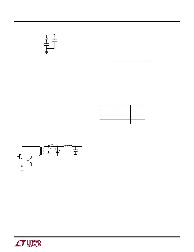
�V� IN�
�T1�
�1:N�
�D� S1�
�V� SEC�
�D� S2�
�L� O�
�+�
�C� O�
�V� OUT�
�case� diode� forward� drop� (V� F� )� and� switch-on� voltage� (V� SW� ).�
�There� are� a� number� of� ways� to� choose� the� inductance�
�value� for� L� O� .� We� suggest� as� a� starting� point� that� L� O� be�
�Q1A�
�selected� such� that� the� converter� is� continuous� at�
�Q1B�
�1533� F04�
�I� OUT(MAX)� /4.� If� your� minimum� I� OUT� is� higher� than� this,� or�
�you� are� operating� at� low� currents� such� that� the� IC� and�
�components� can� handle� higher� peak� currents,� then� use� a�
�Figure� 4�
�The� following� definitions� will� be� used:�
�V� IN� =� Input� supply� voltage�
�V� SW� =� Switch-on� voltage�
�V� OUT� =� Desired� output� voltage�
�I� OUT� =� Output� current�
�f� =� Oscillator� frequency�
�V� F� =� Forward� drop� of� the� rectifier�
�Duty� cycle� is� the� major� defining� equation� for� this� topology.�
�Note� that� the� output� L� and� C� basically� filter� the� chopped�
�higher� number.�
�Continuous� operation� occurs� when� the� current� in� the�
�inductor� never� goes� to� zero.� Discontinuous� operation�
�occurs� when� the� inductor� current� drops� to� zero� before� the�
�start� of� the� next� cycle� and� can� occur� with� small� inductors�
�and� light� loads.� There� is� nothing� inherently� bad� about�
�discontinuous� operation,� however,� the� converter� control�
�and� operation� is� somewhat� different.� The� inductor� is�
�smaller� for� discontinuous� operation� but� the� peak� currents�
�in� the� switch,� the� transformer,� the� diodes,� inductor� and�
�capacitor� will� be� higher.� But� for� low� power� situations� these�
�may� not� present� a� big� constraint.�
�voltage� so� duty� cycle� controls� output� voltage.� N� is� the�
�11�
�相关PDF资料 |
PDF描述 |
|---|---|
| MAX6424UK50+T | IC MPU/RESET CIRC 5.00V SOT23-5 |
| LTC3415EUHF#PBF | IC REG BUCK SYNC ADJ 7A 38QFN |
| HCP0704-R60-R | INDUCTOR HI CURNT 0.60UH 14A SMD |
| HCC26DREH | CONN EDGECARD 52POS .100 EYELET |
| VE-J1K-EY-F2 | CONVERTER MOD DC/DC 40V 50W |
相关代理商/技术参数 |
参数描述 |
|---|---|
| LT1534 | 制造商:LINER 制造商全称:Linear Technology 功能描述:Ultralow Noise 2A Switching Regulators |
| LT1534-1 | 制造商:LINER 制造商全称:Linear Technology 功能描述:Ultralow Noise 2A Switching Regulators |
| LT-1534-501-024 | 制造商:Carling Technologies 功能描述:LT-SERIES TOGGLE SWITCH - Bulk |
| LT-1534-510-012 | 制造商:Carling Technologies 功能描述:LT-SERIES TOGGLE SWITCH - Bulk |
| LT-1534-510-024 | 制造商:Carling Technologies 功能描述:LT-SERIES TOGGLE SWITCH - Bulk |
发布紧急采购,3分钟左右您将得到回复。