- 您现在的位置:买卖IC网 > PDF目录2155 > LT1886CS8#TRPBF (Linear Technology)IC OPAMP DUAL 200MA 700MHZ 8SOIC PDF资料下载
参数资料
| 型号: | LT1886CS8#TRPBF |
| 厂商: | Linear Technology |
| 文件页数: | 16/16页 |
| 文件大小: | 0K |
| 描述: | IC OPAMP DUAL 200MA 700MHZ 8SOIC |
| 标准包装: | 2,500 |
| 放大器类型: | 通用 |
| 电路数: | 2 |
| 转换速率: | 200 V/µs |
| 增益带宽积: | 700MHz |
| 电流 - 输入偏压: | 1.5µA |
| 电压 - 输入偏移: | 1000µV |
| 电流 - 电源: | 7mA |
| 电流 - 输出 / 通道: | 800mA |
| 电压 - 电源,单路/双路(±): | 4 V ~ 13 V,±2 V ~ 6.5 V |
| 工作温度: | 0°C ~ 70°C |
| 安装类型: | 表面贴装 |
| 封装/外壳: | 8-SOIC(0.154",3.90mm 宽) |
| 供应商设备封装: | 8-SO |
| 包装: | 带卷 (TR) |
9
LT1886
Input Considerations
The inputs of the LT1886 are an NPN differential pair
protected by back-to-back diodes (see the Simplified
Schematic). There are no series protection resistors
onboard which would degrade the input voltage noise. If
the inputs can have a voltage difference of more than 0.7V,
the input current should be limited to less than 10mA with
external resistance (usually the feedback resistor or source
resistor). Each input also has two ESD clamp diodes—one
to each supply. If an input drive exceeds the supply, limit
the current with an external resistor to less than 10mA.
The LT1886 design is a true operational amplifier with high
impedance inputs and low input bias currents. The input
offset current is a factor of ten lower than the input bias
current. To minimize offsets due to input bias currents,
match the equivalent DC resistance seen by both inputs.
The low input noise current can significantly reduce total
noise compared to a current feedback amplifier, especially
for higher source resistances.
Layout and Passive Components
With a gain bandwidth product of 700MHz the LT1886
requires attention to detail in order to extract maximum
performance. Use a ground plane, short lead lengths and
a combination of RF-quality supply bypass capacitors
(i.e., 470pF and 0.1
F). As the primary applications have
high drive current, use low ESR supply bypass capacitors
(1
F to 10F). For best distortion performance with high
drive current a capacitor with the shortest possible trace
lengths should be placed between Pins 4 and 8. The
optimum location for this capacitor is on the back side of
the PC board. The DSL driver demo board (DC304) for this
part uses a Taiyo Yuden 10
Fceramic(TMK432BJ106MM).
The parallel combination of the feedback resistor and gain
setting resistor on the inverting input can combine with
the input capacitance to form a pole which can cause
frequency peaking. In general, use feedback resistors of
1k
or less.
Thermal Issues
The LT1886 enhanced
θJA SO-8 package has the V– pin
fused to the lead frame. This thermal connection increases
the efficiency of the PC board as a heat sink. The PCB
material can be very effective at transmitting heat between
the pad area attached to the V– pin and a ground or power
plane layer. Copper board stiffeners and plated through-
holes can also be used to spread the heat generated by the
device. Table 1 lists the thermal resistance for several
different board sizes and copper areas. All measurements
were taken in still air on 3/32" FR-4 board with 2oz copper.
This data can be used as a rough guideline in estimating
thermal resistance. The thermal resistance for each appli-
cation will be affected by thermal interactions with other
components as well as board size and shape.
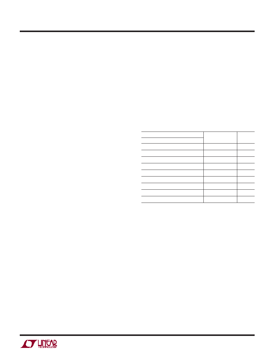
Table 1. Fused 8-Lead SO Package
COPPER AREA (2oz)
TOTAL
TOPSIDE
BACKSIDE
COPPER AREA
θJA
2500 sq. mm
5000 sq. mm
80
°C/W
1000 sq. mm
2500 sq. mm
3500 sq. mm
92°C/W
600 sq. mm
2500 sq. mm
3100 sq. mm
96°C/W
180 sq. mm
2500 sq. mm
2680 sq. mm
98°C/W
180 sq. mm
1000 sq. mm
1180 sq. mm
112°C/W
180 sq. mm
600 sq. mm
780 sq. mm
116°C/W
180 sq. mm
300 sq. mm
480 sq. mm
118°C/W
180 sq. mm
100 sq. mm
280 sq. mm
120°C/W
180 sq. mm
0 sq. mm
180 sq. mm
122°C/W
Calculating Junction Temperature
The junction temperature can be calculated from the
equation:
TJ = (PD)(θJA) + TA
TJ = Junction Temperature
TA = Ambient Temperature
PD = Device Dissipation
θJA = Thermal Resistance (Junction-to-Ambient)
As an example, calculate the junction temperature for the
circuit in Figure 1 assuming an 85
°Cambienttemperature.
The device dissipation can be found by measuring the
supply currents, calculating the total dissipation and then
subtracting the dissipation in the load.
APPLICATIO S I FOR ATIO
WU
U
相关PDF资料 |
PDF描述 |
|---|---|
| LT1920IS8#TRPBF | IC AMP INSTRUMENT PREC LP 8SOIC |
| LT1969CMS#TRPBF | IC OP-AMP ADJ CURRNT DUAL 10MSOP |
| LT1970IFE#TRPBF | IC OP AMP 500MA ADJ 20-TSSOP |
| LT1990AHS8#TRPBF | IC AMP DIFF +/-250V MCRPWR 8SOIC |
| LT1993CUD-10#TRPBF | IC DIFF AMP/ADC DRVR 16-QFN |
相关代理商/技术参数 |
参数描述 |
|---|---|
| LT1893-11-0125 | 制造商:未知厂家 制造商全称:未知厂家 功能描述:PHOTOTRANSISTOR | NPN | DOME-5.0 |
| LT18E-Q21-LU0X3-H1141 | 制造商:TURCK Inc 功能描述:LT0102 |
| LT190 | 制造商:Cooper Wiring Devices 功能描述: |
| LT190Z | 制造商:SEOUL 制造商全称:Seoul Semiconductor 功能描述:GREEN OVAL LAMP LED |
| LT191 | 制造商:SEOUL 制造商全称:Seoul Semiconductor 功能描述:BLUE OVAL LAMP LED |
发布紧急采购,3分钟左右您将得到回复。