- 您现在的位置:买卖IC网 > PDF目录15242 > LT3748EMS#PBF (Linear Technology)IC REG CTRLR FLYBK ISO CM 16MSOP PDF资料下载
参数资料
| 型号: | LT3748EMS#PBF |
| 厂商: | Linear Technology |
| 文件页数: | 15/30页 |
| 文件大小: | 0K |
| 描述: | IC REG CTRLR FLYBK ISO CM 16MSOP |
| 产品培训模块: | LT3748 100V Flyback Controller |
| 特色产品: | LT3748 Isolated Flyback Controller |
| 标准包装: | 37 |
| PWM 型: | 电流模式 |
| 输出数: | 1 |
| 电源电压: | 5 V ~ 100 V |
| 降压: | 无 |
| 升压: | 无 |
| 回扫: | 是 |
| 反相: | 无 |
| 倍增器: | 无 |
| 除法器: | 无 |
| Cuk: | 无 |
| 隔离: | 是 |
| 工作温度: | -40°C ~ 125°C |
| 封装/外壳: | 16-TFSOP(0.118",3.00mm),12 引线 |
| 包装: | 管件 |
| 配用: | 732-3308-ND - BOARD EVAL FOR LT3748 732-3305-ND - BOARD EVAL FOR LT3748 |
| 相关产品: | 732-2669-2-ND - TRANS FLYBACK LT3748 20UH SMD 732-2669-6-ND - TRANS FLYBACK LT3748 20UH SMD 732-2668-6-ND - TRANS FLYBACK LT3748 14UH SMD 732-2667-6-ND - TRANS FLYBACK LT3748 500UH SMD 732-2666-6-ND - TRANS FLYBACK LT3748 12UH SMD 732-2665-6-ND - TRANS FLYBACK LT3748 12UH SMD 732-2664-6-ND - TRANS FLYBACK LT3748 15UH SMD 732-2663-6-ND - TRANS FLYBACK LT3748 15UH SMD 732-2662-6-ND - TRANS FLYBACK LT3748 8UH SMD 732-2661-6-ND - TRANS FLYBACK LT3748 8UH SMD 更多... |
第1页第2页第3页第4页第5页第6页第7页第8页第9页第10页第11页第12页第13页第14页当前第15页第16页第17页第18页第19页第20页第21页第22页第23页第24页第25页第26页第27页第28页第29页第30页
�� �
�
�LT3748�
�APPLICATIONS� INFORMATION�
�Saturation� Current�
�As� discussed� earlier� in� the� Maximum� Output� Power� sec-�
�tion,� because� the� core� of� the� transformer� is� being� used� for�
�the� observed� periods� (t� PERIOD� ,� and� t� PERIOD(SNUBBED)� )� and�
�snubber� capacitance� (C� SNUBBER� )� is� below,� and� the� resultant�
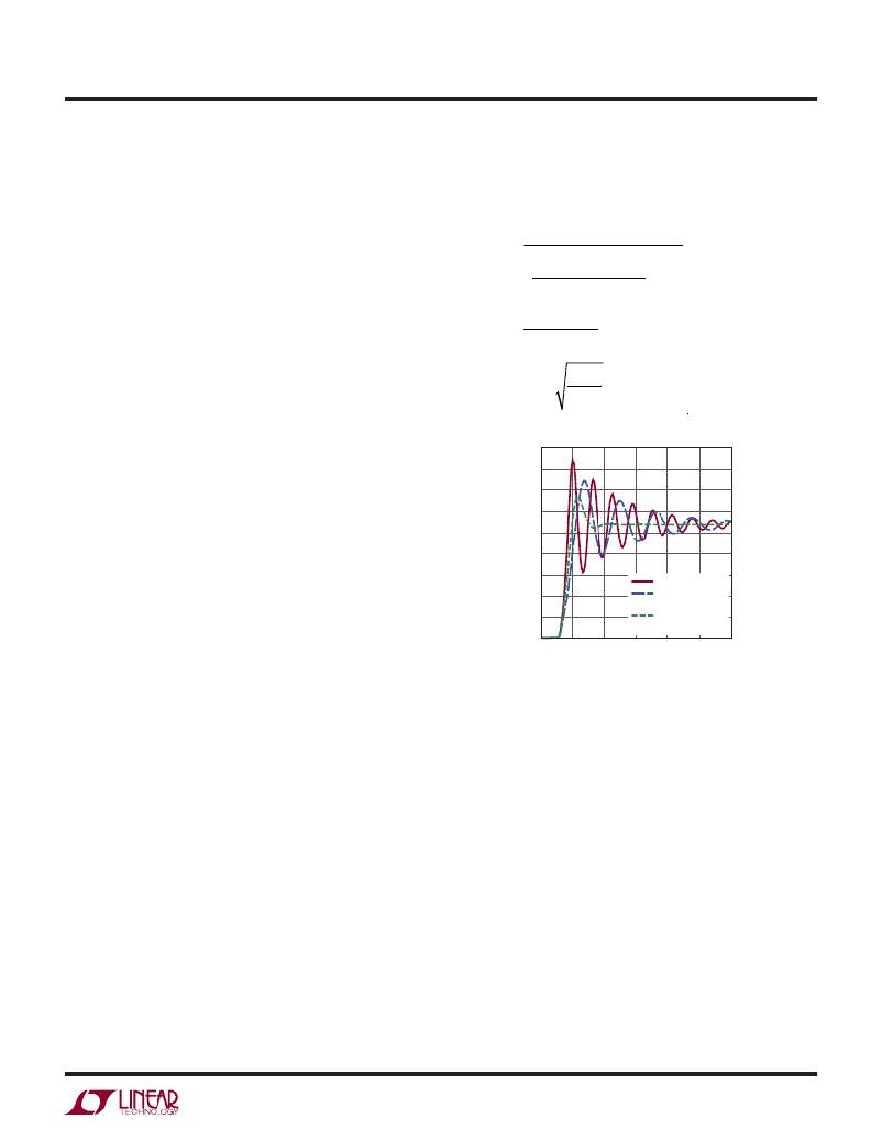
�waveforms� are� shown� in� Figure� 6.�
�energy� storage� in� a� flyback,� the� current� in� the� transformer�
�windings� should� not� exceed� their� rated� saturation� current�
�as� energy� injected� once� the� core� is� saturated� will� not� be�
�transferred� to� the� secondary� and� will� instead� be� dissipated�
�in� the� core.� Information� on� saturation� current� should� be�
�provided� by� the� transformer� manufacturers� and� Table� 1�
�lists� the� saturation� current� of� the� transformers� designed�
�C� PAR� =�
�L� PAR� =�
�C� SNUBBER�
�?� t� PERIOD(SNUBBED)� ?� 2�
�?� ?� –1�
�?� t� PERIOD� ?�
�t� PERIOD2�
�C� PAR� ?� 4� π� 2�
�for� use� with� the� LT3748.�
�Leakage� Inductance� and� Snubbers�
�Transformer� leakage� inductance� (on� either� the� primary�
�or� secondary)� causes� a� voltage� spike� to� appear� at� the�
�primary� after� the� MOSFET� switch� turns� off.� This� spike� is�
�increasingly� prominent� at� higher� load� currents� where� more�
�stored� energy� must� be� dissipated.� Transformer� leakage�
�inductance� should� be� minimized.�
�In� most� cases,� proper� selection� of� the� external� MOSFET�
�and� a� well� designed� transformer� will� eliminate� the� need� for�
�snubber� circuitry,� but� in� some� cases� the� optimal� MOSFET�
�R� SNUBBER� =�
�90�
�80�
�70�
�60�
�50�
�40�
�30�
�20�
�10�
�L� PAR�
�C� PAR�
�NO� SNUBBER�
�WITH� SNUBBER�
�CAPACITOR�
�WITH� RESISTOR�
�may� require� protection� from� this� leakage� spike.� An� RC�
�(resistor� capacitor)� snubber� may� be� sufficient� in� applica-�
�tions� where� the� MOSFET� has� significant� margin� beyond�
�0�
�0�
�0.05�
�0.10�
�0.15�
�TIME� (μs)�
�AND� CAPACITOR�
�0.20� 0.25� 0.30�
�3748� F06�
�the� predicted� DC� drain� voltage� applied� in� flyback� while� a�
�clamp� using� an� RCD� (resistor� capacitor� diode)� or� a� Zener�
�might� be� a� better� option� when� using� a� MOSFET� with� very�
�little� margin� for� leakage� inductance� spiking.�
�The� recommended� approach� for� designing� an� RC� snubber�
�is� to� measure� the� period� of� the� ringing� at� the� MOSFET� drain�
�when� the� MOSFET� turns� off� without� the� snubber� and� then�
�add� capacitance—starting� with� something� in� the� range� of�
�100pF—until� the� period� of� the� ringing� is� 1.5� to� 2� times�
�longer.� The� change� in� period� will� determine� the� value� of� the�
�parasitic� capacitance,� from� which� the� parasitic� inductance�
�can� be� determined� from� the� initial� period,� as� well.� Similarly,�
�initial� values� can� be� estimating� using� stated� switch� capaci-�
�tance� and� transformer� leakage� inductance.� Once� the� value�
�of� the� drain� node� capacitance� and� inductance� is� known,� a�
�series� resistor� can� be� added� to� the� snubber� capacitance�
�to� dissipate� power� and� critically� dampen� the� ringing.� The�
�equation� for� deriving� the� optimal� series� resistance� using�
�Figure� 6.� Observed� Waveforms� at� MOSFET� Drain� when�
�Iteratively� Implementing� an� RC� Snubber�
�Note� that� energy� absorbed� by� a� snubber� will� be� converted�
�to� heat� and� will� not� be� delivered� to� the� load.� In� high� volt-�
�age� or� high� current� applications,� the� snubber� may� need� to�
�be� sized� for� thermal� dissipation.� To� determine� the� power�
�dissipated� in� the� snubber� resistor� from� capacitive� losses,�
�measure� the� drain� voltage� immediately� before� the� MOSFET�
�turns� on� and� use� the� following� equation� relating� that� volt-�
�age� and� the� MOSFET� switching� frequency� to� determine�
�the� expected� power� dissipation:�
�P� SNUBBER� =� f� SW� ?� C� SNUBBER� ?� V� DRAIN2� /2�
�Decreasing� the� value� of� the� capacitor� will� reduce� the� dis-�
�sipated� power� in� the� snubber� at� the� expense� of� increased�
�peak� voltage� on� the� MOSFET� drain,� while� increasing� the�
�value� of� the� capacitance� will� decrease� the� overshoot.�
�3748fa�
�15�
�相关PDF资料 |
PDF描述 |
|---|---|
| H2AAT-10104-R4-ND | JUMPER-H1502TR/A2015R/H1502TR 4" |
| H2AAT-10104-N4-ND | JUMPER-H1502TR/A2015N/H1502TR 4" |
| H2AAT-10104-L4-ND | JUMPER-H1502TR/A2015L/H1502TR 4" |
| VE-J7J-EY-F4 | CONVERTER MOD DC/DC 36V 50W |
| LTC1436AIGN-PLL#PBF | IC REG CTRLR BUCK PWM CM 24-SSOP |
相关代理商/技术参数 |
参数描述 |
|---|---|
| LT3748EMSTRPBF | 制造商:LINER 制造商全称:Linear Technology 功能描述:100V Isolated Flyback Controller |
| LT3748HMS#PBF | 功能描述:IC REG CTRLR FLYBK ISO CM 16MSOP RoHS:是 类别:集成电路 (IC) >> PMIC - 稳压器 - DC DC 切换控制器 系列:- 特色产品:LM3753/54 Scalable 2-Phase Synchronous Buck Controllers 标准包装:1 系列:PowerWise® PWM 型:电压模式 输出数:1 频率 - 最大:1MHz 占空比:81% 电源电压:4.5 V ~ 18 V 降压:是 升压:无 回扫:无 反相:无 倍增器:无 除法器:无 Cuk:无 隔离:无 工作温度:-5°C ~ 125°C 封装/外壳:32-WFQFN 裸露焊盘 包装:Digi-Reel® 产品目录页面:1303 (CN2011-ZH PDF) 其它名称:LM3754SQDKR |
| LT3748HMS#TRPBF | 功能描述:IC REG CTRLR FLYBK ISO CM 16MSOP RoHS:是 类别:集成电路 (IC) >> PMIC - 稳压器 - DC DC 切换控制器 系列:- 标准包装:4,500 系列:PowerWise® PWM 型:控制器 输出数:1 频率 - 最大:1MHz 占空比:95% 电源电压:2.8 V ~ 5.5 V 降压:是 升压:无 回扫:无 反相:无 倍增器:无 除法器:无 Cuk:无 隔离:无 工作温度:-40°C ~ 125°C 封装/外壳:6-WDFN 裸露焊盘 包装:带卷 (TR) 配用:LM1771EVAL-ND - BOARD EVALUATION LM1771 其它名称:LM1771SSDX |
| LT3748HMSPBF | 制造商:LINER 制造商全称:Linear Technology 功能描述:100V Isolated Flyback Controller |
| LT3748HMSTRPBF | 制造商:LINER 制造商全称:Linear Technology 功能描述:100V Isolated Flyback Controller |
发布紧急采购,3分钟左右您将得到回复。