- 您现在的位置:买卖IC网 > PDF目录149343 > LTC1430CS#PBF (LINEAR TECHNOLOGY CORP) Isolated Flyback Switching Regulator with 9V Output PDF资料下载
参数资料
| 型号: | LTC1430CS#PBF |
| 厂商: | LINEAR TECHNOLOGY CORP |
| 元件分类: | 稳压器 |
| 英文描述: | Isolated Flyback Switching Regulator with 9V Output |
| 中文描述: | SWITCHING CONTROLLER, 500 kHz SWITCHING FREQ-MAX, PDSO16 |
| 封装: | 0.150 INCH, PLASTIC, SO-16 |
| 文件页数: | 3/16页 |
| 文件大小: | 211K |
| 代理商: | LTC1430CS#PBF |
11
LTC1430
pensation components. In general, a smaller value induc-
tor will improve transient response at the expense of ripple
and inductor core saturation rating. Minimizing output
capacitor ESR will also help optimize output transient
response. See Input and Output Capacitors for more
information.
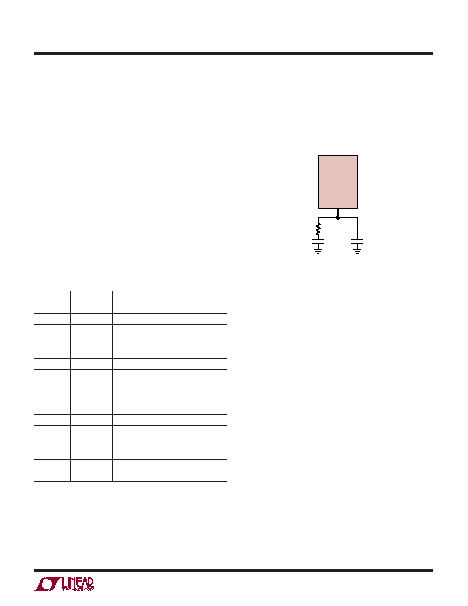
Compensation and Transient Response
The LTC1430 voltage feedback loop is compensated at the
COMP pin; this is the output node of the internal gm error
amplifier. The loop can generally be compensated prop-
erly with an RC network from COMP to GND and an
additional small C from COMP to GND (Figure 8). Loop
stability is affected by inductor and output capacitor
values and by other factors. Optimum loop response can
be obtained by using a network analyzer to find the loop
poles and zeros; nearly as effective and a lot easier is to
empirically tweak the RC values until the transient recovery
looks right with an output load step. Table 1 shows
recommended compensation components for 5V to 3.3V
applications based on the inductor and output capacitor
values. The values were calculated using multiple paral-
leled 330
F AVX TPS series surface mount tantalum
capacitors as the output capacitor.
Table 1. Recommended Compensation Network for 5V to 3.3V
Application Using Multiple 330
F AVX Output Capacitors
L1 (
H)
COUT (F)
RC (k)CC (F)
C1 (pF)
1
990
1.8
0.022
820
1
1980
3.6
0.01
470
1
4950
9.1
0.0047
150
1
9900
18
0.0022
82
2.7
990
3.6
0.01
470
2.7
1980
7.5
0.0047
220
2.7
4950
18
0.0022
82
2.7
9900
39
0.001
39
5.6
990
9.1
0.0047
150
5.6
1980
18
0.0022
82
5.6
4950
47
820pF
33
5.6
9900
91
470pF
15
10
990
18
0.0022
82
10
1980
39
0.001
39
10
4950
91
470pF
15
10
9900
180
220pF
10
Output transient response is set by three major factors: the
time constant of the inductor and the output capacitor, the
more impact on overall transient recovery time than the
third; unless the loop compensation is way off, more
improvement can be had by optimizing the inductor and
the output capacitor than by fiddling with the loop com-
LTC1430
COMP
GND
SGND LTC1430 F08
C1
CC
RC
Figure 8. Compensation Pin Hook-Up
Soft-Start and Current Limit
The 16-lead versions of the LTC1430 include a soft-start
circuit at the SS pin; this circuit is used both for initial start-
up and during current limit operation. The soft-start and
current limit circuitry is disabled in 8-lead versions. SS
requires an external capacitor to GND with the value
determined by the required soft-start time. An internal
12
A current source is included to charge the external
capacitor. Soft-start functions by clamping the maximum
voltage that the COMP pin can swing to, thereby control-
ling the duty cycle (Figure 9). The LTC1430 will begin to
operate at low duty cycle as the SS pin rises to about 2V
below VCC. As SS continues to rise, the duty cycle will
increase until the error amplifier takes over and begins to
regulate the output. When SS reaches 1V below VCC the
LTC1430 will be in full operation. An internal switch shorts
the SS pin to GND during shutdown.
The LTC1430 detects the output current by watching the
voltage at IFB while M1 is ON. The ILIM amplifier compares
this voltage to the voltage at IMAX (Figure 10). In the ON
state, M1 has a known resistance; by calculating back-
wards, the voltage generated at IFB by the maximum
output current in M1 can be determined. As IFB falls below
IMAX, ILIM will begin to sink current from the soft-start pin,
APPLICATIO S I FOR ATIO
WU
U
相关PDF资料 |
PDF描述 |
|---|---|
| LTC1430IS#PBF | Isolated Flyback Switching Regulator with 9V Output |
| LTC1430IS#TRPBF | Isolated Flyback Switching Regulator with 9V Output |
| LTC1435AIG#TRPBF | High Efficiency Low Noise Synchronous Step-Down Switching Regulator |
| LTC1435AIS#TRPBF | High Efficiency Low Noise Synchronous Step-Down Switching Regulator |
| LTC1436ACGN#PBF | RADIATION HARDENED HIGH EFFICIENCY, 5 AMP SWITCHING REGULATORS |
相关代理商/技术参数 |
参数描述 |
|---|---|
| LTC1430CSTR | 制造商:LT 功能描述:* |
| LTC1430IS | 功能描述:IC SW REG CNTRLR STEP-DWN 16SOIC RoHS:否 类别:集成电路 (IC) >> PMIC - 稳压器 - 专用型 系列:- 标准包装:43 系列:- 应用:控制器,Intel VR11 输入电压:5 V ~ 12 V 输出数:1 输出电压:0.5 V ~ 1.6 V 工作温度:-40°C ~ 85°C 安装类型:表面贴装 封装/外壳:48-VFQFN 裸露焊盘 供应商设备封装:48-QFN(7x7) 包装:管件 |
| LTC1430IS#PBF | 功能描述:IC SW REG CNTRLR STEP-DWN 16SOIC RoHS:是 类别:集成电路 (IC) >> PMIC - 稳压器 - 专用型 系列:- 标准包装:43 系列:- 应用:控制器,Intel VR11 输入电压:5 V ~ 12 V 输出数:1 输出电压:0.5 V ~ 1.6 V 工作温度:-40°C ~ 85°C 安装类型:表面贴装 封装/外壳:48-VFQFN 裸露焊盘 供应商设备封装:48-QFN(7x7) 包装:管件 |
| LTC1430IS#TR | 功能描述:IC SW REG CNTRLR STEP-DWN 16SOIC RoHS:否 类别:集成电路 (IC) >> PMIC - 稳压器 - 专用型 系列:- 标准包装:43 系列:- 应用:控制器,Intel VR11 输入电压:5 V ~ 12 V 输出数:1 输出电压:0.5 V ~ 1.6 V 工作温度:-40°C ~ 85°C 安装类型:表面贴装 封装/外壳:48-VFQFN 裸露焊盘 供应商设备封装:48-QFN(7x7) 包装:管件 |
| LTC1430IS#TRPBF | 功能描述:IC SW REG CNTRLR STEP-DWN 16SOIC RoHS:是 类别:集成电路 (IC) >> PMIC - 稳压器 - 专用型 系列:- 标准包装:43 系列:- 应用:控制器,Intel VR11 输入电压:5 V ~ 12 V 输出数:1 输出电压:0.5 V ~ 1.6 V 工作温度:-40°C ~ 85°C 安装类型:表面贴装 封装/外壳:48-VFQFN 裸露焊盘 供应商设备封装:48-QFN(7x7) 包装:管件 |
发布紧急采购,3分钟左右您将得到回复。