- 您现在的位置:买卖IC网 > PDF目录15236 > LTC1438XCG (Linear Technology)IC REG CTRLR BUCK PWM CM 28-SSOP PDF资料下载
参数资料
| 型号: | LTC1438XCG |
| 厂商: | Linear Technology |
| 文件页数: | 13/32页 |
| 文件大小: | 0K |
| 描述: | IC REG CTRLR BUCK PWM CM 28-SSOP |
| 标准包装: | 47 |
| PWM 型: | 电流模式 |
| 输出数: | 2 |
| 频率 - 最大: | 138kHz |
| 占空比: | 99% |
| 电源电压: | 3.5 V ~ 30 V |
| 降压: | 是 |
| 升压: | 无 |
| 回扫: | 无 |
| 反相: | 无 |
| 倍增器: | 无 |
| 除法器: | 无 |
| Cuk: | 无 |
| 隔离: | 无 |
| 工作温度: | 0°C ~ 70°C |
| 封装/外壳: | 28-SSOP(0.209",5.30mm 宽) |
| 包装: | 管件 |
第1页第2页第3页第4页第5页第6页第7页第8页第9页第10页第11页第12页当前第13页第14页第15页第16页第17页第18页第19页第20页第21页第22页第23页第24页第25页第26页第27页第28页第29页第30页第31页第32页
�� �
�
�LTC1438/LTC1439�
�APPLICATIO� N� S� I� N� FOR� M� ATIO� N�
�Accepting� larger� values� of� ?� I� L� allows� the� use� of� low�
�inductances,� but� results� in� higher� output� voltage� ripple�
�and� greater� core� losses.� A� reasonable� starting� point� for�
�setting� ripple� current� is� ?� I� L� =� 0.4(I� MAX� ).� Remember,� the�
�maximum� ?� I� L� occurs� at� the� maximum� input� voltage.�
�The� inductor� value� also� has� an� effect� on� low� current�
�operation.� The� transition� to� low� current� operation� begins�
�when� the� inductor� current� reaches� zero� while� the� bottom�
�MOSFET� is� on.� Lower� inductor� values� (higher� ?� I� L� )� will�
�cause� this� to� occur� at� higher� load� currents,� which� can�
�cause� a� dip� in� efficiency� in� the� upper� range� of� low� current�
�operation.� In� Burst� Mode� operation� (TGS1,� 2� pins� open),�
�lower� inductance� values� will� cause� the� burst� frequency� to�
�decrease.�
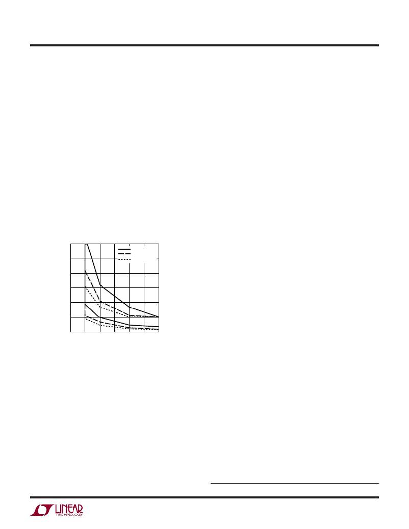
�The� Figure� 3� graph� gives� a� range� of� recommended� induc-�
�tor� values� vs� operating� frequency� and� V� OUT� .�
�60�
�Ferrite� designs� have� very� low� core� loss� and� are� preferred�
�at� high� switching� frequencies,� so� design� goals� can� con-�
�centrate� on� copper� loss� and� preventing� saturation.� Ferrite�
�core� material� saturates� “hard,”� which� means� that� induc-�
�tance� collapses� abruptly� when� the� peak� design� current� is�
�exceeded.� This� results� in� an� abrupt� increase� in� inductor�
�ripple� current� and� consequent� output� voltage� ripple.� Do�
�not� allow� the� core� to� saturate!�
�Molypermalloy� (from� Magnetics,� Inc.)� is� a� very� good,� low�
�loss� core� material� for� toroids,� but� it� is� more� expensive� than�
�ferrite.� A� reasonable� compromise� from� the� same� manu-�
�facturer� is� Kool� M� μ� .� Toroids� are� very� space� efficient,�
�especially� when� you� can� use� several� layers� of� wire.� Be-�
�cause� they� generally� lack� a� bobbin,� mounting� is� more�
�difficult.� However,� designs� for� surface� mount� are� available�
�which� do� not� increase� the� height� significantly.�
�Power� MOSFET� and� D1� Selection�
�50�
�40�
�30�
�20�
�10�
�V� OUT� =� 5.0V�
�V� OUT� =� 3.3V�
�V� OUT� =� 2.5V�
�Three� external� power� MOSFETs� must� be� selected� for� each�
�controller� with� the� LTC1439:� a� pair� of� N-channel� MOSFETs�
�for� the� top� (main)� switch� and� an� N-channel� MOSFET� for�
�the� bottom� (synchronous)� switch.� Only� one� top� MOSFET�
�is� required� for� each� LTC1438� controller.�
�To� take� advantage� of� the� Adaptive� Power� output� stage,� two�
�topside� MOSFETs� must� be� selected.� A� large� [low� R� SD(ON)� ]�
�MOSFET� and� a� small� [higher� R� DS(ON)� ]� MOSFET� are� re-�
�0�
�0�
�50� 100� 150� 200� 250�
�OPERATING� FREQUENCY� (kHz)�
�300�
�quired.� The� large� MOSFET� is� used� as� the� main� switch� and�
�works� in� conjunction� with� the� synchronous� switch.� The�
�1438� F03�
�Figure� 3.� Recommended� Inductor� Values�
�Inductor� Core� Selection�
�Once� the� value� for� L� is� known,� the� type� of� inductor� must� be�
�selected.� High� efficiency� converters� generally� cannot� af-�
�ford� the� core� loss� found� in� low� cost� powdered� iron� cores,�
�forcing� the� use� of� more� expensive� ferrite,� molypermalloy�
�or� Kool� M� μ� ?� cores.� Actual� core� loss� is� independent� of� core�
�size� for� a� fixed� inductor� value,� but� it� is� very� dependent� on�
�inductance� selected.� As� inductance� increases,� core� losses�
�go� down.� Unfortunately,� increased� inductance� requires� more�
�turns� of� wire� and� therefore� copper� losses� will� increase.�
�smaller� MOSFET� is� only� enabled� under� low� load� current�
�conditions.� The� benefit� of� this� is� to� boost� low� to� midcurrent�
�efficiencies� while� continuing� to� operate� at� constant� fre-�
�quency.� Also,� by� using� the� small� MOSFET� the� circuit� will�
�keep� switching� at� a� constant� frequency� down� to� lower�
�currents� and� delay� skipping� cycles.�
�The� R� DS(ON)� recommended� for� the� small� MOSFET� is�
�around� 0.5� ?� .� Be� careful� not� to� use� a� MOSFET� with� an�
�R� DS(ON)� that� is� too� low;� remember,� we� want� to� conserve�
�gate� charge.� (A� higher� R� DS(ON)� MOSFET� has� a� smaller� gate�
�capacitance� and� thus� requires� less� current� to� charge� its�
�gate).� For� all� LTC1438� and� cost� sensitive� LTC1439� appli-�
�cations,� the� small� MOSFET� is� not� required.� The� circuit� then�
�begins� Burst� Mode� operation� as� the� load� current� drops.�
�Kool� M� μ� is� a� registered� trademark� of� Magnetics,� Inc.�
�14389fb�
�13�
�相关PDF资料 |
PDF描述 |
|---|---|
| H2AAT-10104-R8-ND | JUMPER-H1502TR/A3048R/H1502TR 4" |
| ISC1210EB180J | INDUCTOR WW 18UH 5% 1210 |
| LTC1629IG-PG#TR | IC REG CTRLR BUCK PWM CM 28-SSOP |
| LTC1629IG-PG#TRPBF | IC REG CTRLR BUCK PWM CM 28-SSOP |
| LTC1629IG#TRPBF | IC REG CTRLR BUCK PWM CM 28-SSOP |
相关代理商/技术参数 |
参数描述 |
|---|---|
| LTC1438XCG#PBF | 功能描述:IC REG CTRLR BUCK PWM CM 28-SSOP RoHS:是 类别:集成电路 (IC) >> PMIC - 稳压器 - DC DC 切换控制器 系列:- 标准包装:4,500 系列:PowerWise® PWM 型:控制器 输出数:1 频率 - 最大:1MHz 占空比:95% 电源电压:2.8 V ~ 5.5 V 降压:是 升压:无 回扫:无 反相:无 倍增器:无 除法器:无 Cuk:无 隔离:无 工作温度:-40°C ~ 125°C 封装/外壳:6-WDFN 裸露焊盘 包装:带卷 (TR) 配用:LM1771EVAL-ND - BOARD EVALUATION LM1771 其它名称:LM1771SSDX |
| LTC1438XCG#TR | 功能描述:IC REG CTRLR BUCK PWM CM 28-SSOP RoHS:否 类别:集成电路 (IC) >> PMIC - 稳压器 - DC DC 切换控制器 系列:- 标准包装:4,500 系列:PowerWise® PWM 型:控制器 输出数:1 频率 - 最大:1MHz 占空比:95% 电源电压:2.8 V ~ 5.5 V 降压:是 升压:无 回扫:无 反相:无 倍增器:无 除法器:无 Cuk:无 隔离:无 工作温度:-40°C ~ 125°C 封装/外壳:6-WDFN 裸露焊盘 包装:带卷 (TR) 配用:LM1771EVAL-ND - BOARD EVALUATION LM1771 其它名称:LM1771SSDX |
| LTC1438XCG#TRPBF | 功能描述:IC REG CTRLR BUCK PWM CM 28-SSOP RoHS:是 类别:集成电路 (IC) >> PMIC - 稳压器 - DC DC 切换控制器 系列:- 标准包装:4,500 系列:PowerWise® PWM 型:控制器 输出数:1 频率 - 最大:1MHz 占空比:95% 电源电压:2.8 V ~ 5.5 V 降压:是 升压:无 回扫:无 反相:无 倍增器:无 除法器:无 Cuk:无 隔离:无 工作温度:-40°C ~ 125°C 封装/外壳:6-WDFN 裸露焊盘 包装:带卷 (TR) 配用:LM1771EVAL-ND - BOARD EVALUATION LM1771 其它名称:LM1771SSDX |
| LTC1439CG | 功能描述:IC REG CTRLR BUCK PWM CM 36-SSOP RoHS:否 类别:集成电路 (IC) >> PMIC - 稳压器 - DC DC 切换控制器 系列:- 标准包装:2,000 系列:- PWM 型:电流模式 输出数:1 频率 - 最大:1MHz 占空比:50% 电源电压:9 V ~ 10 V 降压:无 升压:是 回扫:是 反相:无 倍增器:无 除法器:无 Cuk:无 隔离:无 工作温度:-40°C ~ 85°C 封装/外壳:8-TSSOP(0.173",4.40mm 宽) 包装:带卷 (TR) |
| LTC1439CG#PBF | 功能描述:IC REG CTRLR BUCK PWM CM 36-SSOP RoHS:是 类别:集成电路 (IC) >> PMIC - 稳压器 - DC DC 切换控制器 系列:- 标准包装:2,000 系列:- PWM 型:电流模式 输出数:1 频率 - 最大:1MHz 占空比:50% 电源电压:9 V ~ 10 V 降压:无 升压:是 回扫:是 反相:无 倍增器:无 除法器:无 Cuk:无 隔离:无 工作温度:-40°C ~ 85°C 封装/外壳:8-TSSOP(0.173",4.40mm 宽) 包装:带卷 (TR) |
发布紧急采购,3分钟左右您将得到回复。