- 您现在的位置:买卖IC网 > PDF目录17165 > LTC1559CGN-5#TRPBF (Linear Technology)IC BACKUP BATT CNTRLR 5V 16-SSOP PDF资料下载
参数资料
| 型号: | LTC1559CGN-5#TRPBF |
| 厂商: | Linear Technology |
| 文件页数: | 8/20页 |
| 文件大小: | 0K |
| 描述: | IC BACKUP BATT CNTRLR 5V 16-SSOP |
| 标准包装: | 2,500 |
| 功能: | 备份管理 |
| 电池化学: | 镍镉 |
| 电源电压: | 4.4 V ~ 5.5 V |
| 工作温度: | 0°C ~ 70°C |
| 安装类型: | 表面贴装 |
| 封装/外壳: | 16-SSOP(0.154",3.90mm 宽) |
| 供应商设备封装: | 16-SSOP |
| 包装: | 带卷 (TR) |
�� �
�
�LTC1559-3.3/LTC1559-5�
�APPLICATIO� N� S� I� N� FOR� M� ATIO� N�
�Overview�
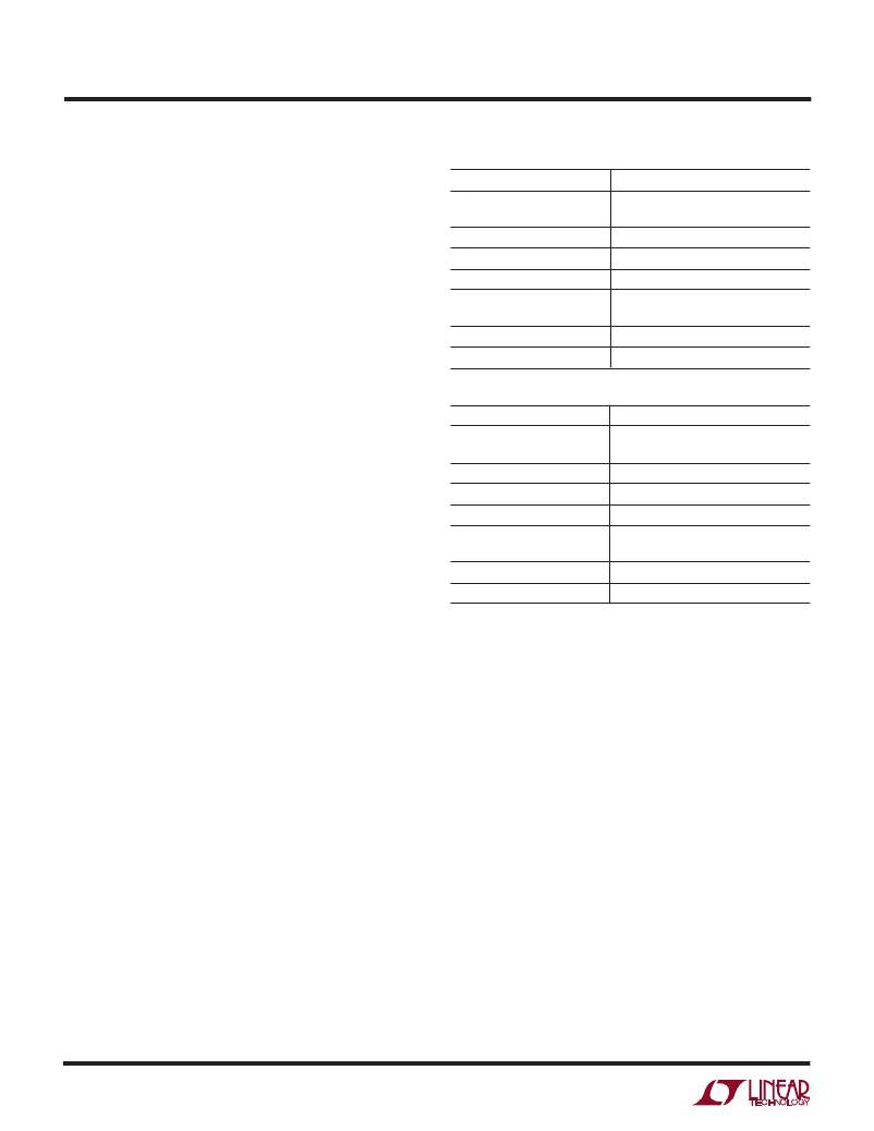
�Table� 1.� LTC1559-3.3� Operating� Modes�
�The� LTC1559� is� a� versatile� backup� battery� control� system�
�designed� to� provide� all� the� functions� necessary� to� imple-�
�ment� a� complete,� highly� integrated� backup� system� within�
�a� single� chip.� It� allows� the� system� to� maintain� its� rated�
�supply� voltage� during� backup,� offering� maximum� sys-�
�tem� design� flexibility.� The� LTC1559� allows� the� use� of� a�
�low� cost� rechargeable� NiCd� cell� for� backup,� eliminating�
�the� need� for� expensive,� replaceable� 4.5V� lithium� backup�
�cells.�
�The� LTC1559� includes� an� onboard� boost� converter�
�OPERATING� MODES�
�UVLO� Reset�
�Push-Button� Reset�
�UVLO� Reset� Recovery�
�Backup� Mode� Activation�
�Backup� Mode� Exit�
�Boost� Converter� Activation�
�Boost� Converter� Deactivation�
�CONDITIONS�
�1V� <� V� CC� <� V� CC� (rated� value)� –� 9%� or�
�V� BAT� <� 0.9V�
�V� CTL� <� 250mV�
�V� CC� >� V� CC� (rated� value)� –� 5.5%�
�V� CC� <� V� CC� (rated� value)� –� 7%�
�V� CC� >� V� CC� (rated� value)� –� 5.5%�
�or� PS� >� V� CC�
�V� CC� <� V� CC� (rated� value)� –� 7%�
�V� CC� >� V� CC� (rated� value)� –� 7%�
�designed� to� generate� a� fixed� voltage� (3.07V� for� 3.3V� parts�
�Table� 2.� LTC1559-5� Operating� Modes�
�and� 4.625V� for� 5V� parts)� from� a� single� 1.2V� NiCd� cell.�
�When� connected� to� the� system� DC/DC� converter’s� output,�
�the� LTC1559� enables� the� system� connected� to� the� V� CC� rail�
�to� continue� operation� when� the� main� power� supply� fails.� A�
�“smart”� recharging� circuit� uses� an� accumulating� gas�
�gauge� to� measure� the� charge� extracted� from� the� backup�
�battery� during� a� backup� cycle.� This� measured� charge� is�
�then� replaced� in� a� fast� recharge� cycle,� without� wasting�
�excess� power� or� overcharging� the� backup� cell.� An� exter-�
�nally� adjustable� trickle� charge� circuit� maintains� the� cell�
�charge� after� the� fast� charge� cycle� has� completed,� minimiz-�
�OPERATING� MODES�
�UVLO� Reset�
�Push-Button� Reset�
�UVLO� Reset� Recovery�
�Backup� Mode� Activation�
�Backup� Mode� Exit�
�Boost� Converter� Activation�
�Boost� Converter� Deactivation�
�CONDITIONS�
�1V� <� V� CC� <� V� CC� (rated� value)� –� 9%�
�or� V� BAT� <� 0.9V�
�V� CTL� <� 250mV�
�V� CC� >� V� CC� (rated� value)� –� 6%�
�V� CC� <� V� CC� (rated� value)� –� 7.5%�
�V� CC� >� V� CC� (rated� value)� –� 6%�
�or� PS� >� V� CC�
�V� CC� <� V� CC� (rated� value)� –� 7.5%�
�V� CC� >� V� CC� (rated� value)� –� 7.5%�
�ing� drain� from� the� main� battery� during� standby.�
�Included� in� the� LTC1559� is� a� complete� backup� circuit� that�
�monitors� the� main� system� power� and� automatically�
�switches� in� the� backup� circuit� as� the� primary� power� supply�
�falls� away� (due� to� a� weak� or� disconnected� main� battery).�
�The� LTC1559� also� performs� V� CC� supervisory� functions�
�during� normal� system� operations.� An� LTC1559-3.3�
�monitors� a� 3.3V� supply� voltage� at� its� V� CC� pin� while� an�
�LTC1559-5� monitors� a� 5V� supply� at� its� V� CC� pin.� In� both�
�cases,� the� LTC1559� derives� power� for� the� majority� of� the�
�internal� circuitry� (except� for� the� boost� converter)� from� its�
�V� CC� pin.� Table� 1� shows� the� signal� conditions� for� the�
�various� operating� modes� of� the� LTC1559-3.3.� Table� 2�
�shows� the� signal� conditions� for� the� various� operating�
�modes� of� the� LTC1559-5.�
�Boost� Converter� Operation�
�The� LTC1559� uses� an� onboard� boost� converter� with� a�
�fixed� peak� current� architecture� that� provides� a� simple� and�
�flexible� system� solution� while� eliminating� the� need� for�
�conventional� frequency� compensation.� The� boost�
�converter’s� output,� set� to� 93%� (LTC1559-3.3)� or� 92.5%�
�(LTC1559-5)� of� the� rated� V� CC� ,� supports� the� system� V� CC�
�during� backup.� It� supplies� a� minimum� backup� power� of�
�100mW.� The� boost� converter� operates� in� a� modified�
�pulse-skipping� mode;� each� switch� cycle� transfers� a� known�
�amount� of� charge� from� the� backup� cell� to� the� regulated�
�output.� This� prevents� uncontrolled� discharge� of� the� backup�
�cell� and� allows� the� LTC1559� to� accurately� measure� the�
�charge� removed� from� the� backup� cell� by� counting� the�
�charge� pulses.�
�The� LTC1559� enters� backup� mode� when� the� main� battery�
�voltage� drops� and� causes� V� CC� ,� the� system� regulator’s�
�output,� to� fall.� As� shown� in� Figure� 1,� V� CC� is� scaled� down�
�by� an� internal� resistor� divider� and� fed� to� the� LTC1559’s�
�backup� comparators.� These� compare� the� scaled� voltage�
�8�
�相关PDF资料 |
PDF描述 |
|---|---|
| V375C15C75BF2 | CONVERTER MOD DC/DC 15V 75W |
| 12RS473C | INDUCT RAD 47UH 2.2A T/H 10X10 |
| HSC08DRYN-S13 | CONN EDGECARD 16POS .100 EXTEND |
| 12RS683C | INDUCT RAD 68UH 1.8A T/H 10X10 |
| V375C15C75BL3 | CONVERTER MOD DC/DC 15V 75W |
相关代理商/技术参数 |
参数描述 |
|---|---|
| LTC1559CS-3.3 | 功能描述:IC BACKUP BATT CNTRLR3.3V 16SOIC RoHS:否 类别:集成电路 (IC) >> PMIC - 电池管理 系列:- 标准包装:61 系列:- 功能:电源管理 电池化学:锂离子(Li-Ion)、锂聚合物(Li-Pol) 电源电压:4.35 V ~ 5.5 V 工作温度:-40°C ~ 85°C 安装类型:表面贴装 封装/外壳:22-WFDFN 裸露焊盘 供应商设备封装:22-DFN(6x3)裸露焊盘 包装:管件 |
| LTC1559CS-3.3#PBF | 功能描述:IC BACKUP BATT CNTRLR3.3V 16SOIC RoHS:是 类别:集成电路 (IC) >> PMIC - 电池管理 系列:- 标准包装:1 系列:- 功能:充电管理 电池化学:锂离子(Li-Ion)、锂聚合物(Li-Pol) 电源电压:3.75 V ~ 6 V 工作温度:-40°C ~ 85°C 安装类型:表面贴装 封装/外壳:SC-74A,SOT-753 供应商设备封装:SOT-23-5 包装:剪切带 (CT) 产品目录页面:669 (CN2011-ZH PDF) 其它名称:MCP73831T-2ACI/OTCT |
| LTC1559CS-3.3#TRPBF | 功能描述:IC BACKUP BATT CNTRLR3.3V 16SOIC RoHS:是 类别:集成电路 (IC) >> PMIC - 电池管理 系列:- 标准包装:1 系列:- 功能:充电管理 电池化学:锂离子(Li-Ion)、锂聚合物(Li-Pol) 电源电压:3.75 V ~ 6 V 工作温度:-40°C ~ 85°C 安装类型:表面贴装 封装/外壳:SC-74A,SOT-753 供应商设备封装:SOT-23-5 包装:剪切带 (CT) 产品目录页面:669 (CN2011-ZH PDF) 其它名称:MCP73831T-2ACI/OTCT |
| LTC1559CS-5 | 功能描述:IC BACKUP BATT CNTRLR 5V 16-SOIC RoHS:否 类别:集成电路 (IC) >> PMIC - 电池管理 系列:- 标准包装:61 系列:- 功能:电源管理 电池化学:锂离子(Li-Ion)、锂聚合物(Li-Pol) 电源电压:4.35 V ~ 5.5 V 工作温度:-40°C ~ 85°C 安装类型:表面贴装 封装/外壳:22-WFDFN 裸露焊盘 供应商设备封装:22-DFN(6x3)裸露焊盘 包装:管件 |
| LTC1559CS-5#PBF | 功能描述:IC BACKUP BATT CNTRLR 5V 16-SOIC RoHS:是 类别:集成电路 (IC) >> PMIC - 电池管理 系列:- 标准包装:1 系列:- 功能:充电管理 电池化学:锂离子(Li-Ion)、锂聚合物(Li-Pol) 电源电压:3.75 V ~ 6 V 工作温度:-40°C ~ 85°C 安装类型:表面贴装 封装/外壳:SC-74A,SOT-753 供应商设备封装:SOT-23-5 包装:剪切带 (CT) 产品目录页面:669 (CN2011-ZH PDF) 其它名称:MCP73831T-2ACI/OTCT |
发布紧急采购,3分钟左右您将得到回复。