- 您现在的位置:买卖IC网 > PDF目录15327 > LTC1700EMS#TRPBF (Linear Technology)IC REG CTRLR BST PWM CM 10-MSOP PDF资料下载
参数资料
| 型号: | LTC1700EMS#TRPBF |
| 厂商: | Linear Technology |
| 文件页数: | 9/16页 |
| 文件大小: | 0K |
| 描述: | IC REG CTRLR BST PWM CM 10-MSOP |
| 标准包装: | 2,500 |
| PWM 型: | 电流模式 |
| 输出数: | 1 |
| 频率 - 最大: | 680kHz |
| 占空比: | 92% |
| 电源电压: | 0.9 V ~ 6 V |
| 降压: | 无 |
| 升压: | 是 |
| 回扫: | 无 |
| 反相: | 无 |
| 倍增器: | 无 |
| 除法器: | 无 |
| Cuk: | 无 |
| 隔离: | 无 |
| 工作温度: | -40°C ~ 85°C |
| 封装/外壳: | 10-TFSOP,10-MSOP(0.118",3.00mm 宽) |
| 包装: | 带卷 (TR) |
�� �
�
�LTC1700�
�APPLICATIO� N� S� I� N� FOR� M� ATIO� N�
�load� current.� When� the� LTC1700� is� operating� in� continu-�
�ous� mode,� the� duty� cycles� for� the� MOSFETs� are:�
�Main� MOSFET� Duty� Cycle� =� 1� –� V� IN� /V� OUT�
�Synchronous� MOSFET� Duty� Cycle� =� V� IN� /V� OUT�
�The� MOSFET� power� dissipations� at� maximum� output�
�current� are:�
�P� MAIN� =� (1� –� V� IN� /V� OUT� )(I� O(MAX)2� )(� ρ� T(MAIN)� )(R� DS(ON)� )�
�+� (k)(V� 0UT2� )(I� O(MAX)� )C� RSS� (f)�
�P� SYNC� =� (V� IN� /V� OUT� )(I� O(MAX)2� )(� ρ� T(BOT)� )(R� DS(ON)� )�
�Both� MOSFETs� have� I� 2� R� losses� and� the� P� MAIN� equation�
�includes� an� additional� term� for� transition� losses,� which� are�
�largest� at� high� output� voltages.� The� constant� k� =� 2.5� can� be�
�used� to� estimate� the� amount� of� transition� loss.� The� syn-�
�chronous� MOSFET� losses� are� greatest� at� high� input� volt-�
�age� and� low� output� voltage.�
�Start-Up� Load� Current�
�In� start-up� mode,� the� current� limit� is� set� at� 60mA� and� the�
�oscillator� runs� at� 210kHz� with� 50%� duty� cycle� at�
�V� IN� =� 1.8V.� Since� the� current� limit� is� low,� the� amount� of�
�energy� that� is� stored� in� the� inductor� during� the� on� time� is�
�small.� Therefore� the� LTC1700� is� incapable� of� supplying�
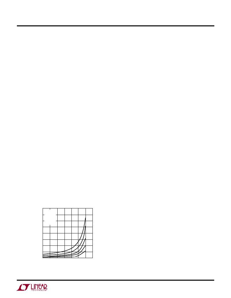
�the� full� load� current.� Figure� 4� shows� the� amount� of� load�
�current� the� LTC1700� can� provide� while� successfully� exit-�
�ing� out� of� the� start-up� mode.� If� the� load� current� exceeds�
�the� amount� shown� in� Figure� 4� during� start-up,� the� output�
�voltage� will� not� increase� but� will� “hang”� at� a� value� below�
�the� regulated� voltage.� However,� if� the� load� current� is� lower,�
�40�
�A� =� 15� μ� H�
�then� there� is� a� net� positive� amount� of� energy� stored� in� the�
�output� capacitor� for� every� cycle.� The� output� voltage� then�
�rises� and� once� it� exceeds� 2.3V,� the� LTC1700� will� success-�
�fully� exit� out� of� its� start-up� mode.�
�Operating� Frequency� and� Synchronization�
�The� choice� of� operating� frequency� and� inductor� value� is� a�
�trade-off� between� efficiency� and� component� size.� Low�
�frequency� operation� improves� efficiency� by� reducing�
�MOSFET� switching� losses,� both� gate� charge� loss� and�
�transition� loss.� However,� lower� frequency� operation� re-�
�quires� more� inductance� for� a� given� amount� of� ripple�
�current.�
�The� internal� oscillator� runs� at� a� nominal� 530kHz� frequency�
�when� the� SYNC/MODE� pin� is� either� connected� to� GND� or�
�V� IN� .� When� a� CMOS� compatible� clock� is� applied� to� the�
�SYNC/MODE� pin,� the� internal� oscillator� will� lock� on� to� the�
�external� clock.� The� LTC1700� uses� a� novel� technique� to�
�phase� lock� to� the� external� clock� without� the� requirement� of�
�an� external� PLL� filter,� hence� minimizing� components.� The�
�capture� range� is� between� 400kHz� to� 750kHz.� Do� not�
�synchronize� below� or� above� the� capture� range� as� this� will�
�cause� abnormal� operation.� During� synchronization,� Burst�
�Mode� operation� is� inhibited.�
�The� LTC1700� will� lock� on� at� the� leading� edge� of� the� external�
�clock� and� the� minimum� pulse� width� required� is�
�200ns.�
�Remember� just� because� you� can� operate� at� a� high� switch-�
�ing� frequency� doesn’t� always� mean� you� should.� At� higher�
�frequencies� the� switching� loss� increases,� so� the� C� RSS� of�
�the� N-channel� MOSFET� becomes� very� critical� to� keep�
�35�
�30�
�25�
�20�
�15�
�10�
�5�
�B� =� 10� μ� H�
�C� =� 6.2� μ� H�
�D� =� 4.2� μ� H�
�E� =� 2.2� μ� H�
�A�
�B�
�C�
�D�
�E�
�efficiencies� high.�
�Slope� Compensation� and� Peak� Inductor� Current�
�Current� mode� switching� regulators� that� operate� with� a�
�duty� cycle� greater� than� 50%� with� continuous� inductor�
�current� can� exhibit� duty� cycle� instability.� While� the� regu-�
�lator� will� not� be� damaged� and� may� even� continue� to�
�function� acceptably,� a� look� at� its� frequency� spectrum�
�0�
�1.0�
�1.2�
�1.4�
�1.6�
�1.8�
�2.0�
�2.2�
�2.4�
�will� indicate� harmonics.� These� harmonics� may� interfere�
�V� IN� (V)�
�1700� ?� G04�
�with� other� sensitive� devices� and� will� cause� non-optimal�
�performance.�
�Figure� 4.� Start-Up� Load� Current�
�1700fa�
�9�
�相关PDF资料 |
PDF描述 |
|---|---|
| LTC3852IUDD#PBF | IC REG CTRLR DOUBLER PWM 24-QFN |
| VI-JWT-EY-F2 | CONVERTER MOD DC/DC 6.5V 50W |
| ADM802MARN | IC SUPERVISOR MPU 4.40V WD 8SOIC |
| IMC1210BN180J | INDUCTOR WW 18UH 5% 1210 |
| LTC3808EGN#PBF | IC REG CTRLR BUCK PWM CM 16-SSOP |
相关代理商/技术参数 |
参数描述 |
|---|---|
| LTC1701BES5 | 制造商:Linear Technology 功能描述:1.1 A SWITCHING REGULATOR, 1000 kHz SWITCHING FREQ-MAX, PDSO5 |
| LTC1701BES5#PBF | 制造商:Linear Technology 功能描述:Conv DC-DC Single Step Down 2.5V to 5.5V 5-Pin TSOT-23 制造商:Linear Technology 功能描述:DP-SWREG/Monolithic, CUT TAPE 1MHz Step-dn DC/DC Con in SOT-23 |
| LTC1701BES5#TR | 功能描述:IC REG BUCK ADJ 0.5A TSOT23-5 RoHS:否 类别:集成电路 (IC) >> PMIC - 稳压器 - DC DC 开关稳压器 系列:- 标准包装:2,500 系列:- 类型:升压(升压) 输出类型:可调式 输出数:1 输出电压:1.24 V ~ 30 V 输入电压:1.5 V ~ 12 V PWM 型:电流模式,混合 频率 - 开关:600kHz 电流 - 输出:500mA 同步整流器:无 工作温度:-40°C ~ 85°C 安装类型:表面贴装 封装/外壳:8-SOIC(0.154",3.90mm 宽) 包装:带卷 (TR) 供应商设备封装:8-SOIC |
| LTC1701BES5#TRM | 功能描述:IC REG BUCK ADJ 0.5A TSOT23-5 RoHS:否 类别:集成电路 (IC) >> PMIC - 稳压器 - DC DC 开关稳压器 系列:- 标准包装:2,500 系列:- 类型:升压(升压) 输出类型:可调式 输出数:1 输出电压:1.24 V ~ 30 V 输入电压:1.5 V ~ 12 V PWM 型:电流模式,混合 频率 - 开关:600kHz 电流 - 输出:500mA 同步整流器:无 工作温度:-40°C ~ 85°C 安装类型:表面贴装 封装/外壳:8-SOIC(0.154",3.90mm 宽) 包装:带卷 (TR) 供应商设备封装:8-SOIC |
| LTC1701BES5#TRMPBF | 功能描述:IC REG BUCK ADJ 0.5A TSOT23-5 RoHS:是 类别:集成电路 (IC) >> PMIC - 稳压器 - DC DC 开关稳压器 系列:- 标准包装:2,500 系列:- 类型:升压(升压) 输出类型:可调式 输出数:1 输出电压:1.24 V ~ 30 V 输入电压:1.5 V ~ 12 V PWM 型:电流模式,混合 频率 - 开关:600kHz 电流 - 输出:500mA 同步整流器:无 工作温度:-40°C ~ 85°C 安装类型:表面贴装 封装/外壳:8-SOIC(0.154",3.90mm 宽) 包装:带卷 (TR) 供应商设备封装:8-SOIC |
发布紧急采购,3分钟左右您将得到回复。