- 您现在的位置:买卖IC网 > PDF目录15326 > LTC1771EMS8 (Linear Technology)IC REG CTRLR BUCK PWM CM 8-MSOP PDF资料下载
参数资料
| 型号: | LTC1771EMS8 |
| 厂商: | Linear Technology |
| 文件页数: | 8/16页 |
| 文件大小: | 0K |
| 描述: | IC REG CTRLR BUCK PWM CM 8-MSOP |
| 标准包装: | 50 |
| PWM 型: | 电流模式 |
| 输出数: | 1 |
| 占空比: | 100% |
| 电源电压: | 2.8 V ~ 18 V |
| 降压: | 是 |
| 升压: | 无 |
| 回扫: | 无 |
| 反相: | 无 |
| 倍增器: | 无 |
| 除法器: | 无 |
| Cuk: | 无 |
| 隔离: | 无 |
| 工作温度: | -40°C ~ 85°C |
| 封装/外壳: | 8-TSSOP,8-MSOP(0.118",3.00mm 宽) |
| 包装: | 管件 |
| 其它名称: | Q1164777 |
�� �
�
�LTC1771�
�APPLICATIO� S� I� FOR� ATIO�
�R� DS� (� ON� )� =�
�(� )� (� 1� +� δ� P� )�
�Power MOSFET Selection�
�An� external� P-channel� power� MOSFET� must� be� selected�
�for� use� with� the� LTC1771.� The� main� selection� criteria� for�
�the� power� MOSFET� are� the� threshold� voltage� V� GS(TH)� and�
�the� “on”� resistance� R� DS(ON)� ,� reverse� transfer� capacitance�
�and� total� gate� charge.�
�Since� the� LTC1771� can� operate� down� to� input� voltages� as�
�low� as� 2.8V,� a� sublogic� level� threshold� MOSFET� (R� DS(ON)�
�guaranteed� at� V� GS� =� 2.5V)� is� required� for� applications� that�
�work� close� to� this� voltage.� When� these� MOSFETs� are� used,�
�make� sure� that� the� input� supply� to� the� LTC1771� is� less� than�
�the� absolute� maximum� V� GS� rating� (typically� 12V),� as� the�
�MOSFET� gate� will� see� the� full� supply� voltage.�
�The� required� R� DS(ON)� of� the� MOSFET� is� governed� by� its�
�allowable� power� dissipation.� For� applications� that� may�
�operate� the� LTC1771� in� dropout,� i.e.� 100%� duty� cycle,� at�
�its� worst� case� the� required� R� DS(ON)� is� given� by:�
�P� P�
�2�
�I� OUT� (� MAX� )�
�where� P� P� is� the� allowable� power� dissipation� and� δ� P� is� the�
�temperature� dependency� of� R� DS(ON)� .� (1� +� δ� P� )� is� generally�
�diode� conducts� most� of� the� time.� As� V� IN� approaches� V� OUT�
�the� diode� conducts� only� a� small� fraction� of� the� time.� The�
�most� stressful� condition� for� the� diode� is� when� the� output�
�is� short-circuited.� Under� this� condition,� the� diode� must�
�safely� handle� I� PEAK� at� close� to� 100%� duty� cycle.�
�To� maximize� both� low� and� high� current� efficiencies,� a� fast�
�switching� diode� with� low� forward� drop� and� low� reverse�
�leakage� should� be� used.� Low� reverse� leakage� current� is�
�critical� to� maximize� low� current� efficiency� since� the� leak-�
�age� can� potentially� exceed� the� magnitude� of� the� LTC1771�
�supply� current.� Low� forward� drop� is� critical� for� high�
�current� efficiency� since� loss� is� proportional� to� forward�
�drop.� The� effect� of� reverse� leakage� and� forward� drop� on�
�no-� load� supply� current� and� efficiency� for� various� Schottky�
�diodes� is� shown� in� Table� 1.� As� can� be� seen,� these� are�
�conflicting� parameters� and� the� user� must� weigh� the�
�importance� of� each� spec� in� choosing� the� best� diode� for� the�
�application.�
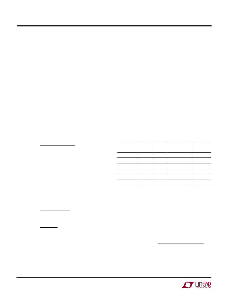
�Table� 1.� Effect� of� Catch� Diode� on� Performance�
�LEAKAGE� NO-LOAD� EFFICIENCY�
�DIODE (V� R� = 3.3V) V� F� @ 1A SUPPLY CURRENT AT 10V/1A�
�MBR0540� 0.25� μ� A� 0.50V� 10.4� μ� A� 86.3%�
�UPS5817� 2.8� μ� A� 0.41V� 11.8� μ� A� 88.2%�
�MBR0520� 3.7� μ� A� 0.36V� 12.2� μ� A� 88.4%�
�given� for� a� MOSFET� in� the� form� of� a� normalized� R� DS(ON)� vs�
�temperature� curve,� but� =� 0.005/� °� C� can� be� used� as� an�
�approximation� for� low� voltage� MOSFETs.�
�MBRS120T3�
�MBRM120LT3�
�MBRS320�
�4.4� μ� A�
�8.3� μ� A�
�19.7� μ� A�
�0.43V�
�0.32V�
�0.29V�
�12.2� μ� A�
�14.0� μ� A�
�20.0� μ� A�
�87.9%�
�89.4%�
�89.8%�
�In� applications� where� the� maximum� duty� cycle� is� less� than�
�100%� and� the� LTC1771� is� in� continuous� mode,� the� R� DS(ON)�
�is� governed� by:�
�C� IN� and� C� OUT� Selection�
�At� higher� load� currents,� when� the� inductor� current� is�
�R� DS� (� ON� )� =�
�DC� =�
�P� P�
�(� DC� )� I� OUT� 2� (� 1� +� δ� P� )�
�V� OUT� +� V� D�
�V� IN� +� V� D�
�continuous,� the� source� current� of� the� P-channel� MOSFET�
�is� a� square� wave� of� duty� cycle� V� OUT� /V� IN� .� To� prevent� large�
�voltage� transients,� a� low� ESR� input� capacitor� sized� for� the�
�maximum� RMS� current� must� be� used.� The� maximum�
�capacitor� current� is� given� by:�
�I� MAX� [� OUT� (� V� IN� ?� V� OUT� )� ]� 1� /� 2�
�where DC is the maximum operating duty cycle of the�
�LTC1771.�
�C� IN� required� I� RMS� =�
�V�
�V� IN�
�Catch� Diode� Selection�
�The� catch� diode� carries� load� current� during� the� off-time.�
�The� average� diode� current� is� therefore� dependent� on� the�
�P-channel� switch� duty� cycle.� At� high� input� voltages� the�
�8�
�This� formula� has� a� maximum� at� V� IN� =� 2V� OUT� ,� where�
�I� RMS� =� I� OUT� /2.� This� simple� worst-case� condition� is� com-�
�monly� used� for� design� because� even� significant� deviations�
�do� not� offer� much� relief.� Note� that� capacitor� manufacturer’s�
�相关PDF资料 |
PDF描述 |
|---|---|
| GMM10DTMN-S273 | CONN EDGECARD 20POS R/A .156 SLD |
| VI-JWT-EY-F4 | CONVERTER MOD DC/DC 6.5V 50W |
| IMC1210BN330J | INDUCTOR WW 33UH 5% 1210 |
| ADM805LARN | IC SUPERVISOR 4.65V WD 8SOIC |
| GSM10DTMD-S273 | CONN EDGECARD 20POS R/A .156 SLD |
相关代理商/技术参数 |
参数描述 |
|---|---|
| LTC1771EMS8#PBF | 功能描述:IC REG CTRLR BUCK PWM CM 8-MSOP RoHS:是 类别:集成电路 (IC) >> PMIC - 稳压器 - DC DC 切换控制器 系列:- 特色产品:LM3753/54 Scalable 2-Phase Synchronous Buck Controllers 标准包装:1 系列:PowerWise® PWM 型:电压模式 输出数:1 频率 - 最大:1MHz 占空比:81% 电源电压:4.5 V ~ 18 V 降压:是 升压:无 回扫:无 反相:无 倍增器:无 除法器:无 Cuk:无 隔离:无 工作温度:-5°C ~ 125°C 封装/外壳:32-WFQFN 裸露焊盘 包装:Digi-Reel® 产品目录页面:1303 (CN2011-ZH PDF) 其它名称:LM3754SQDKR |
| LTC1771EMS8#PBF | 制造商:Linear Technology 功能描述:IC STEP-DOWN DC/DC CONTROLLER MSOP-8 制造商:Linear Technology 功能描述:IC, STEP-DOWN DC/DC CONTROLLER, MSOP-8 |
| LTC1771EMS8#TR | 功能描述:IC REG CTRLR BUCK PWM CM 8-MSOP RoHS:否 类别:集成电路 (IC) >> PMIC - 稳压器 - DC DC 切换控制器 系列:- 标准包装:2,500 系列:- PWM 型:电流模式 输出数:1 频率 - 最大:500kHz 占空比:96% 电源电压:4 V ~ 36 V 降压:无 升压:是 回扫:无 反相:无 倍增器:无 除法器:无 Cuk:无 隔离:无 工作温度:-40°C ~ 125°C 封装/外壳:24-WQFN 裸露焊盘 包装:带卷 (TR) |
| LTC1771EMS8#TRPBF | 功能描述:IC REG CTRLR BUCK PWM CM 8-MSOP RoHS:是 类别:集成电路 (IC) >> PMIC - 稳压器 - DC DC 切换控制器 系列:- 标准包装:2,500 系列:- PWM 型:电流模式 输出数:1 频率 - 最大:500kHz 占空比:96% 电源电压:4 V ~ 36 V 降压:无 升压:是 回扫:无 反相:无 倍增器:无 除法器:无 Cuk:无 隔离:无 工作温度:-40°C ~ 125°C 封装/外壳:24-WQFN 裸露焊盘 包装:带卷 (TR) |
| LTC1771EMS8PBF | 制造商:Linear Technology 功能描述:PWM Controller Current 1.23-18V 5A MSOP8 |
发布紧急采购,3分钟左右您将得到回复。