- 您现在的位置:买卖IC网 > PDF目录15283 > LTC3855IFE#TRPBF (Linear Technology)IC REG CTRLR BUCK PWM CM 38TSSOP PDF资料下载
参数资料
| 型号: | LTC3855IFE#TRPBF |
| 厂商: | Linear Technology |
| 文件页数: | 16/44页 |
| 文件大小: | 0K |
| 描述: | IC REG CTRLR BUCK PWM CM 38TSSOP |
| 标准包装: | 2,000 |
| 系列: | PolyPhase® |
| PWM 型: | 电流模式 |
| 输出数: | 2 |
| 频率 - 最大: | 850kHz |
| 占空比: | 95% |
| 电源电压: | 4.5 V ~ 38 V |
| 降压: | 是 |
| 升压: | 无 |
| 回扫: | 无 |
| 反相: | 无 |
| 倍增器: | 无 |
| 除法器: | 无 |
| Cuk: | 无 |
| 隔离: | 无 |
| 工作温度: | -40°C ~ 125°C |
| 封装/外壳: | 38-TFSOP (0.173",4.40mm 宽)裸露焊盘 |
| 包装: | 带卷 (TR) |
第1页第2页第3页第4页第5页第6页第7页第8页第9页第10页第11页第12页第13页第14页第15页当前第16页第17页第18页第19页第20页第21页第22页第23页第24页第25页第26页第27页第28页第29页第30页第31页第32页第33页第34页第35页第36页第37页第38页第39页第40页第41页第42页第43页第44页
�� �
�
�LTC3855�
�APPLICATIONS� INFORMATION�
�R� SENSE� =�
�?� I� L�
�I� (MAX)� +�
�V� ESL� (� STEP� )� t� ON� ?� t� OFF�
�lessthan1μA.WhentheSENSEpinsrampupfrom0Vto�
�1.4V,� the� small� base� currents� flow� out� of� the� SENSE� pins.�
�When� the� SENSE� pins� ramp� down� from� 12.5V� to� 1.1V,�
�the� small� base� currents� flow� into� the� SENSE� pins.� The�
�high� impedance� inputs� to� the� current� comparators� allow�
�accurate� DCR� sensing.� However,� care� must� be� taken� not�
�to� float� these� pins� during� normal� operation.�
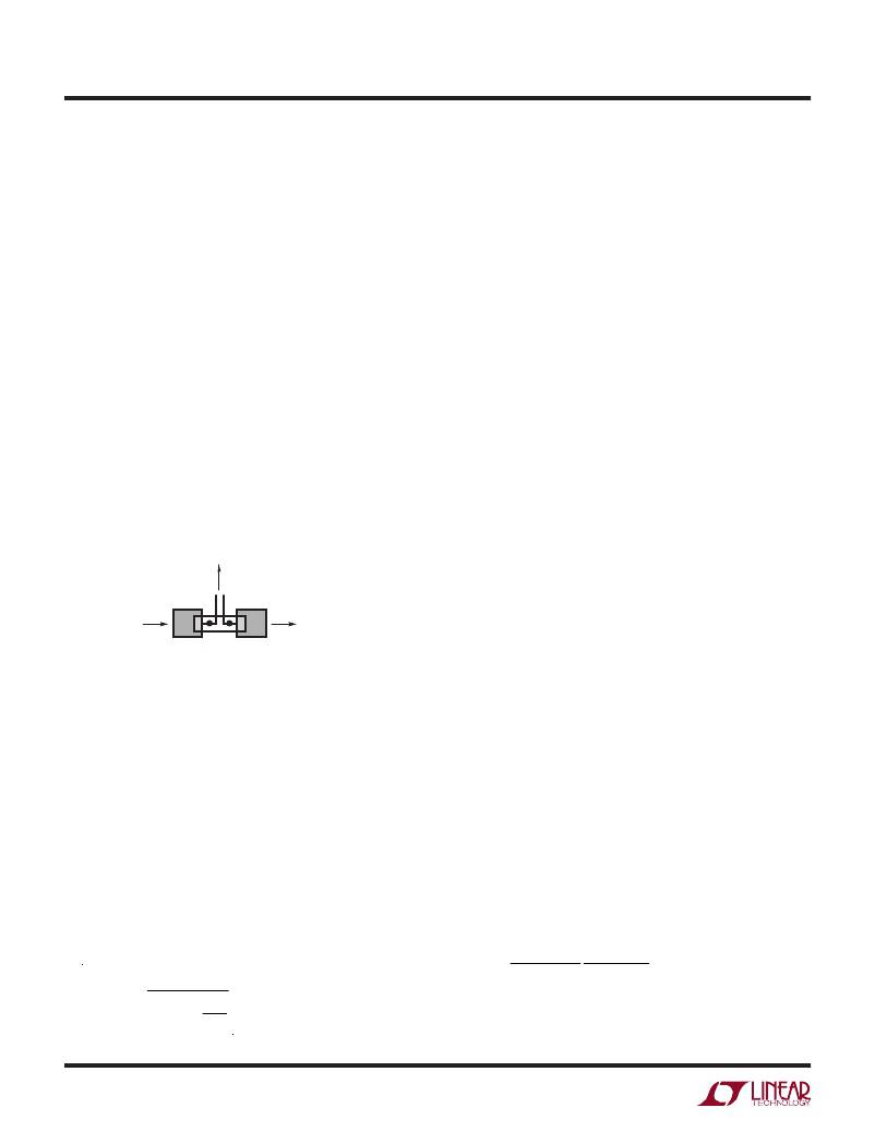
�Filter� components� mutual� to� the� sense� lines� should� be�
�placed� close� to� the� LTC3855,� and� the� sense� lines� should�
�run� close� together� to� a� Kelvin� connection� underneath� the�
�current� sense� element� (shown� in� Figure� 1).� Sensing� cur-�
�rent� elsewhere� can� effectively� add� parasitic� inductance�
�and� capacitance� to� the� current� sense� element,� degrading�
�the� information� at� the� sense� terminals� and� making� the�
�programmed� current� limit� unpredictable.� If� DCR� sensing�
�is� used� (Figure� 2b),� sense� resistor� R1� should� be� placed�
�close� to� the� switching� node,� to� prevent� noise� from� coupling�
�into� sensitive� small-signal� nodes.� The� capacitor� C1� should�
�be� placed� close� to� the� IC� pins.�
�TO� SENSE� FILTER,�
�NEXT� TO� THE� CONTROLLER�
�C� OUT�
�R� SENSE� 3855� F01�
�Figure� 1.� Sense� Lines� Placement� with� Sense� Resistor�
�Low� Value� Resistors� Current� Sensing�
�A� typical� sensing� circuit� using� a� discrete� resistor� is� shown�
�in� Figure� 2a.� R� SENSE� is� chosen� based� on� the� required�
�output� current.�
�The� current� comparator� has� a� maximum� threshold�
�V� SENSE(MAX)� determined� by� the� I� LIM� setting.� The� input�
�common� mode� range� of� the� current� comparator� is� 0V� to�
�12.5V.� The� current� comparator� threshold� sets� the� peak� of�
�the� inductor� current,� yielding� a� maximum� average� output�
�current� I� MAX� equal� to� the� peak� value� less� half� the� peak-to-�
�peak� ripple� current,� ?I� L� .� To� calculate� the� sense� resistor�
�value,� use� the� equation:�
�V� SENSE(MAX)�
�2�
�Because� of� possible� PCB� noise� in� the� current� sensing� loop,�
�the� AC� current� sensing� ripple� of� ?V� SENSE� =� ?I� L� ?� R� SENSE� also�
�needs� to� be� checked� in� the� design� to� get� a� good� signal-to-�
�noise� ratio.� In� general,� for� a� reasonably� good� PCB� layout,� a�
�10mV� ?V� SENSE� voltage� is� recommended� as� a� conservative�
�number� to� start� with,� either� for� R� SENSE� or� DCR� sensing�
�applications,� for� duty� cycles� less� than� 40%.�
�For� previous� generation� current� mode� controllers,� the�
�maximum� sense� voltage� was� high� enough� (e.g.,� 75mV� for�
�the� LTC1628� /� LTC3728� family)� that� the� voltage� drop� across�
�the� parasitic� inductance� of� the� sense� resistor� represented�
�a� relatively� small� error.� For� today’s� highest� current� density�
�solutions,� however,� the� value� of� the� sense� resistor� can�
�be� less� than� 1m?� and� the� peak� sense� voltage� can� be� as�
�low� as� 20mV.� In� addition,� inductor� ripple� currents� greater�
�than� 50%� with� operation� up� to� 1MHz� are� becoming� more�
�common.� Under� these� conditions� the� voltage� drop� across�
�the� sense� resistor’s� parasitic� inductance� is� no� longer� neg-�
�ligible.� A� typical� sensing� circuit� using� a� discrete� resistor� is�
�shown� in� Figure� 2a.� In� previous� generations� of� controllers,�
�a� small� RC� filter� placed� near� the� IC� was� commonly� used� to�
�reduce� the� effects� of� capacitive� and� inductive� noise� coupled�
�inthe� sense� traces� on� the� PCB.� A� typical� filter� consists� of�
�two� series� 10?� resistors� connected� to� a� parallel� 1000pF�
�capacitor,� resulting� in� a� time� constant� of� 20ns.�
�This� same� RC� filter,� with� minor� modifications,� can� be� used�
�to� extract� the� resistive� component� of� the� current� sense�
�signal� in� the� presence� of� parasitic� inductance.� For� example,�
�Figure� 3� illustrates� the� voltage� waveform� across� a� 2m?�
�sense� resistor� with� a� 2010� footprint� for� the� 1.2V/15A�
�converter� operating� at� 100%� load.� The� waveform� is� the�
�superposition� of� a� purely� resistive� component� and� a�
�purely� inductive� component.� It� was� measured� using� two�
�scope� probes� and� waveform� math� to� obtain� a� differential�
�measurement.� Based� on� additional� measurements� of� the�
�inductor� ripple� current� and� the� on-time� and� off-time� of�
�the� top� switch,� the� value� of� the� parasitic� inductance� was�
�determined� to� be� 0.5nH� using� the� equation:�
�ESL� =�
�?� I� L� t� ON� +� t� OFF�
�If� the� RC� time� constant� is� chosen� to� be� close� to� the�
�parasitic� inductance� divided� by� the� sense� resistor� (L/R),�
�3855f�
� �
�相关PDF资料 |
PDF描述 |
|---|---|
| LT3748HMS#TRPBF | IC REG CTRLR FLYBK ISO CM 16MSOP |
| LTC1628CG | IC REG CTRLR BUCK PWM CM 28-SSOP |
| VI-271-EW-F2 | CONVERTER MOD DC/DC 12V 100W |
| LTC1929CG-PG#TR | IC REG CTRLR BUCK PWM CM 28-SSOP |
| VI-271-EW-F1 | CONVERTER MOD DC/DC 12V 100W |
相关代理商/技术参数 |
参数描述 |
|---|---|
| LTC3855IUJ#PBF | 功能描述:IC REG CTRLR BUCK PWM CM 40-QFN RoHS:是 类别:集成电路 (IC) >> PMIC - 稳压器 - DC DC 切换控制器 系列:PolyPhase® 特色产品:LM3753/54 Scalable 2-Phase Synchronous Buck Controllers 标准包装:1 系列:PowerWise® PWM 型:电压模式 输出数:1 频率 - 最大:1MHz 占空比:81% 电源电压:4.5 V ~ 18 V 降压:是 升压:无 回扫:无 反相:无 倍增器:无 除法器:无 Cuk:无 隔离:无 工作温度:-5°C ~ 125°C 封装/外壳:32-WFQFN 裸露焊盘 包装:Digi-Reel® 产品目录页面:1303 (CN2011-ZH PDF) 其它名称:LM3754SQDKR |
| LTC3855IUJ#PBF-ES | 制造商:Linear Technology 功能描述: |
| LTC3855IUJ#TRPBF | 功能描述:IC REG CTRLR BUCK PWM CM 40-QFN RoHS:是 类别:集成电路 (IC) >> PMIC - 稳压器 - DC DC 切换控制器 系列:PolyPhase® 标准包装:2,500 系列:- PWM 型:电流模式 输出数:1 频率 - 最大:500kHz 占空比:96% 电源电压:4 V ~ 36 V 降压:无 升压:是 回扫:无 反相:无 倍增器:无 除法器:无 Cuk:无 隔离:无 工作温度:-40°C ~ 125°C 封装/外壳:24-WQFN 裸露焊盘 包装:带卷 (TR) |
| LTC3856EFE#PBF | 功能描述:IC REG CTRLR BUCK PWM CM 38TFSOP RoHS:是 类别:集成电路 (IC) >> PMIC - 稳压器 - DC DC 切换控制器 系列:PolyPhase® 标准包装:2,000 系列:- PWM 型:电流模式 输出数:1 频率 - 最大:1MHz 占空比:50% 电源电压:9 V ~ 10 V 降压:无 升压:是 回扫:是 反相:无 倍增器:无 除法器:无 Cuk:无 隔离:无 工作温度:-40°C ~ 85°C 封装/外壳:8-TSSOP(0.173",4.40mm 宽) 包装:带卷 (TR) |
| LTC3856EFE#TRPBF | 功能描述:IC REG CTRLR BUCK PWM CM 38TSSOP RoHS:是 类别:集成电路 (IC) >> PMIC - 稳压器 - DC DC 切换控制器 系列:PolyPhase® 标准包装:2,500 系列:- PWM 型:电流模式 输出数:1 频率 - 最大:500kHz 占空比:96% 电源电压:4 V ~ 36 V 降压:无 升压:是 回扫:无 反相:无 倍增器:无 除法器:无 Cuk:无 隔离:无 工作温度:-40°C ~ 125°C 封装/外壳:24-WQFN 裸露焊盘 包装:带卷 (TR) |
发布紧急采购,3分钟左右您将得到回复。