- 您现在的位置:买卖IC网 > PDF目录80307 > LTC4000IGN#TRPBF (LINEAR TECHNOLOGY CORP) 1-CHANNEL POWER SUPPLY MANAGEMENT CKT, PDSO28 PDF资料下载
参数资料
| 型号: | LTC4000IGN#TRPBF |
| 厂商: | LINEAR TECHNOLOGY CORP |
| 元件分类: | 电源管理 |
| 英文描述: | 1-CHANNEL POWER SUPPLY MANAGEMENT CKT, PDSO28 |
| 封装: | 0.150 INCH, LEAD FREE, PLASTIC, SSOP-28 |
| 文件页数: | 6/40页 |
| 文件大小: | 428K |
| 代理商: | LTC4000IGN#TRPBF |
第1页第2页第3页第4页第5页当前第6页第7页第8页第9页第10页第11页第12页第13页第14页第15页第16页第17页第18页第19页第20页第21页第22页第23页第24页第25页第26页第27页第28页第29页第30页第31页第32页第33页第34页第35页第36页第37页第38页第39页第40页
LTC4000
14
4000f
operaTion
The ideal diode behavior is achieved by controlling an
external PMOS connected to the IID pin (drain) and the
CSPpin(source).Thecontroller(A1)regulatestheexternal
PMOS by driving the gate of the PMOS device such that the
voltage drop across IID and CSP is 8mV (typical). When
the external PMOS ability to deliver a particular current
with an 8mV drop across its source and drain is exceeded,
the voltage at the gate clamps at VIGATE(ON) and the PMOS
behaves like a fixed value resistor (RDS(ON)).
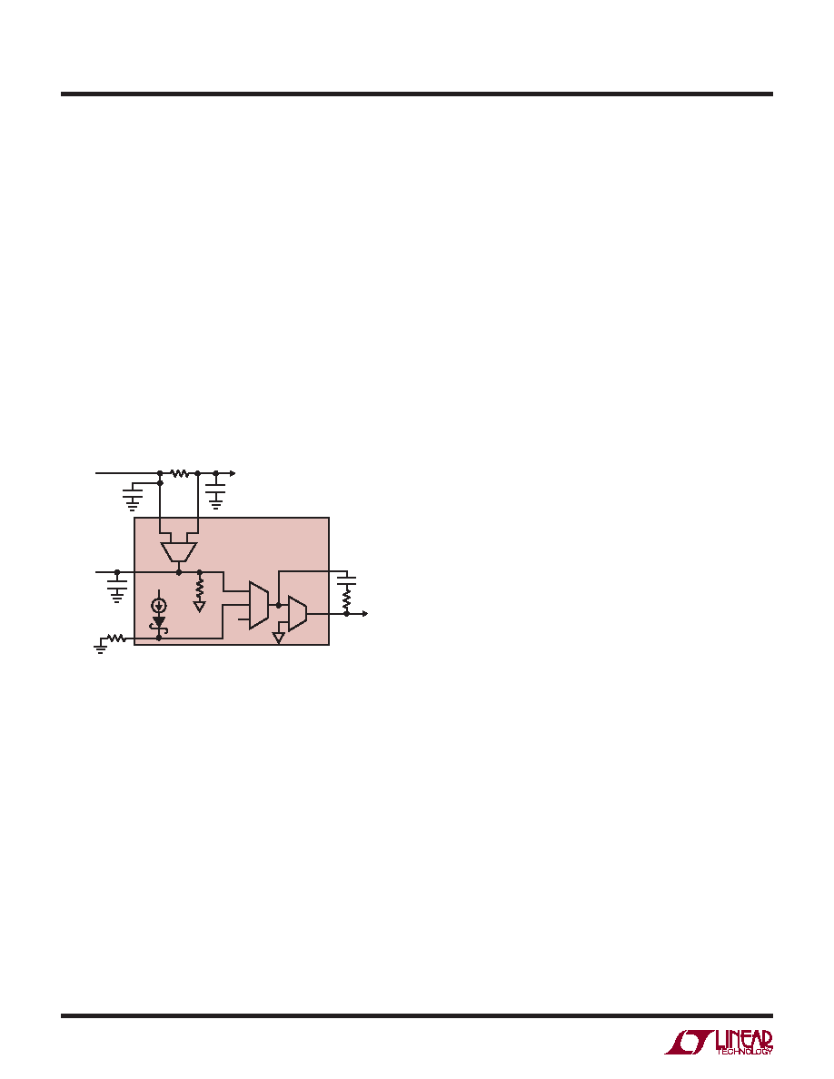
Input Current Regulation and Monitoring
One of the loops driving the ITH and CC pins is the input
current regulation loop (Figure 2). This loop prevents
the input current sensed through the input current sense
resistor (RIS) from exceeding the programmed input
current limit.
OncethebatteryvoltageisaboveVLOBAT,thechargecurrent
regulation loop begins charging in full power constant-
current mode. In this case, the programmed full charge
current is set with a resistor on the CL pin.
Depending on available input power and external load
conditions, the battery charger may not be able to charge
at the full programmed rate. The external load is always
prioritized over the battery charge current. The input
current limit programming is always observed, and only
additional power is available to charge the battery. When
systemloadsarelight,batterychargecurrentismaximized.
Once the float voltage is achieved, the battery float volt-
age regulation loop takes over from the charge current
regulation loop and initiates constant voltage charging. In
constantvoltagecharging,chargecurrentslowlydeclines.
Charge termination can be configured with the TMR pin
in several ways. If the TMR pin is tied to the BIAS pin,
C/X termination is selected. In this case, charging is
terminated when constant voltage charging reduces the
charge current to the C/X level programmed at the CX
pin. Connecting a capacitor to the TMR pin selects the
charge timer termination and a charge termination timer
is started at the beginning of constant voltage charging.
Charging terminates when the termination timer expires.
When continuous charging at the float voltage is desired,
tie the TMR pin to GND to disable termination.
Upon charge termination, the PMOS connected to BGATE
behaves as an ideal diode from BAT to CSN. The diode
function prevents charge current but provides current
to the system load as needed. If the system load can be
completelysuppliedfromtheinput,thebatteryPMOSturns
off. While terminated, if the input current limit is not in
regulation, the output voltage regulation loop takes over to
ensure that the output voltage at CSP remains in control.
The output voltage regulation loop regulates the voltage
at the CSP pin such that the output feedback voltage at
the OFB pin is 1.193V.
If the system load requires more power than is available
from the input, the battery ideal diode controller provides
supplemental power from the battery. When the battery
voltage discharges below 97.1% of the float voltage
(VBFB < VRECHRG(FALL)), the automatic recharge feature
initiates a new charge cycle.
Figure 2. Input Current Regulation Loop
Battery Charger Overview
In addition to the input current regulation loop, the
LTC4000 regulates charge current, battery voltage and
output voltage.
When a battery charge cycle begins, the battery charger
first determines if the battery is over-discharged. If the bat-
tery feedback voltage is below VLOBAT, an automatic trickle
charge feature uses the charge current regulation loop to
set the battery charge current to 10% of the programmed
full scale value. If the TMR pin is connected to a capacitor
or open, the bad battery detection timer is enabled. When
thisbadbatterydetectiontimerexpiresandthebatteryvolt-
age is still below VLOBAT, the battery charger automatically
terminates and indicates, via the FLT and CHRG pins, that
the battery was unresponsive to charge current.
IN
CC
1V
A8
gm = 0.33m
ITH
LTC4000
IN
CLN
RIS
LOAD
CCLN
(OPTIONAL)
IIMON
IL
CIIMON
(OPTIONAL)
CIN
+
–
+
–
CC
TO DC/DC
4000 FO2
RC
60k
50A
BIAS
RIL
A4
相关PDF资料 |
PDF描述 |
|---|---|
| LTC4155EUFD#TRPBF | POWER SUPPLY SUPPORT CKT, PQCC28 |
| LM4040BIZ-5.0AMMOPACK | 1-OUTPUT TWO TERM VOLTAGE REFERENCE, 5 V, PBCY3 |
| L296VH | 4 A SWITCHING REGULATOR, 200 kHz SWITCHING FREQ-MAX, PZFM15 |
| LM9140BYM-2.5 | 1-OUTPUT TWO TERM VOLTAGE REFERENCE, 2.5 V, PDSO8 |
| LK5540-7ERD0TB1 | 2-OUTPUT 150 W AC-DC PWR FACTOR CORR MODULE |
相关代理商/技术参数 |
参数描述 |
|---|---|
| LTC4000IUFD#PBF | 功能描述:IC CHARGER BATTERY 28-QFN RoHS:是 类别:集成电路 (IC) >> PMIC - 电池管理 系列:PowerPath™ 产品培训模块:Lead (SnPb) Finish for COTS Obsolescence Mitigation Program 标准包装:2,500 系列:- 功能:电池监控器 电池化学:碱性,锂离子,镍镉,镍金属氢化物 电源电压:1 V ~ 5.5 V 工作温度:-40°C ~ 85°C 安装类型:表面贴装 封装/外壳:SOT-23-6 供应商设备封装:SOT-6 包装:带卷 (TR) |
| LTC4000IUFD#TRPBF | 功能描述:IC CHARGER BATTERY 28-QFN RoHS:是 类别:集成电路 (IC) >> PMIC - 电池管理 系列:PowerPath™ 产品培训模块:Lead (SnPb) Finish for COTS Obsolescence Mitigation Program 标准包装:2,500 系列:- 功能:电池监控器 电池化学:碱性,锂离子,镍镉,镍金属氢化物 电源电压:1 V ~ 5.5 V 工作温度:-40°C ~ 85°C 安装类型:表面贴装 封装/外壳:SOT-23-6 供应商设备封装:SOT-6 包装:带卷 (TR) |
| LTC4000IUFD-1#PBF | 功能描述:IC BATT CHRGR MULTI-CHEM 28QFN RoHS:是 类别:集成电路 (IC) >> PMIC - 电池管理 系列:PowerPath™ 标准包装:2,000 系列:Impedance Track™ 功能:燃料,电量检测计/监控器 电池化学:锂离子(Li-Ion) 电源电压:2.4 V ~ 2.6 V 工作温度:-40°C ~ 85°C 安装类型:表面贴装 封装/外壳:20-TSSOP(0.173",4.40mm 宽) 供应商设备封装:20-TSSOP 包装:带卷 (TR) 产品目录页面:1020 (CN2011-ZH PDF) 配用:BQ27350EVM-ND - BQ27350EVM 其它名称:296-21665-2 |
| LTC4000IUFD-1#TRPBF | 功能描述:IC CHARGE MGMT MULTI CHEM 28QFN RoHS:是 类别:集成电路 (IC) >> PMIC - 电池管理 系列:PowerPath™ 产品培训模块:Lead (SnPb) Finish for COTS Obsolescence Mitigation Program 标准包装:2,500 系列:- 功能:电池监控器 电池化学:碱性,锂离子,镍镉,镍金属氢化物 电源电压:1 V ~ 5.5 V 工作温度:-40°C ~ 85°C 安装类型:表面贴装 封装/外壳:SOT-23-6 供应商设备封装:SOT-6 包装:带卷 (TR) |
| LTC4001 | 制造商:LINER 制造商全称:Linear Technology 功能描述:2A Synchronous Buck Li-Ion Charger |
发布紧急采购,3分钟左右您将得到回复。