- 您现在的位置:买卖IC网 > PDF目录79689 > LTC4160EUDC#TRPBF (LINEAR TECHNOLOGY CORP) POWER SUPPLY MANAGEMENT CKT, PQCC20 PDF资料下载
参数资料
| 型号: | LTC4160EUDC#TRPBF |
| 厂商: | LINEAR TECHNOLOGY CORP |
| 元件分类: | 电源管理 |
| 英文描述: | POWER SUPPLY MANAGEMENT CKT, PQCC20 |
| 封装: | 3 X 4 MM, 0.75 MM HEIGHT, LEAD FREE, PLASTIC, QFN-20 |
| 文件页数: | 10/32页 |
| 文件大小: | 422K |
| 代理商: | LTC4160EUDC#TRPBF |
第1页第2页第3页第4页第5页第6页第7页第8页第9页当前第10页第11页第12页第13页第14页第15页第16页第17页第18页第19页第20页第21页第22页第23页第24页第25页第26页第27页第28页第29页第30页第31页第32页

LTC4160/LTC4160-1
18
41601fa
the battery will eventually self discharge. To ensure that
the battery is always topped off, a charge cycle will auto-
matically begin when the battery voltage falls below the
recharge threshold which is typically 100mV less than
the charger’s float voltage. In the event that the safety
timer is running when the battery voltage falls below the
recharge threshold, it will reset back to zero. To prevent
brief excursions below the recharge threshold from reset-
ting the safety timer, the battery voltage must be below
the recharge threshold for more than 1ms. The charge
cycle and safety timer will also restart if the VBUS UVLO
cycles low and then high (e.g., VBUS is removed and then
replaced), or if the battery charger is cycled on and off by
the ENCHARGER pin.
Charge Current
The charge current is programmed using a single resis-
tor from PROG to ground. 1/1030th of the battery charge
current is sent to PROG, which will attempt to servo to
1.000V. Thus, the battery charge current will try to reach
1030 times the current in the PROG pin. The program
resistor and the charge current are calculated using the
following equation:
I
V
R
CHG
PROG
=
1030
Ineithertheconstant-currentorconstant-voltagecharging
modes, the voltage at the PROG pin will be proportional to
the actual charge current delivered to the battery. There-
fore, the actual charge current can be determined at any
time by monitoring the PROG pin voltage and using the
following equation:
I
V
R
BAT
PROG
=
1030
In many cases, the actual battery charge current, IBAT, will
be lower than ICHGduetolimitedinputpoweravailableand
prioritization with the system load drawn from VOUT.
The Battery Charger Flow Chart on the next page illustrates
the battery charger’s algorithm.
Charge Status Indication
TheCHRGandFAULTpinscanbeusedtoindicatethestatus
of the battery charger. Two possible states are represented
byCHRG:chargingandnotcharging.Anopen-drainoutput,
the CHRG pin can drive an indicator LED through a current
limiting resistor for human interfacing or simply a pull-up
resistor for microprocessor interfacing.
When charging begins, CHRG is pulled low and remains
low for the duration of a normal charge cycle. When charg-
ing is complete, i.e., the BAT pin reaches the float and the
chargecurrenthasdroppedtoonetenthoftheprogrammed
value, the CHRG pin goes high. The CHRG pin does not
respond to the C/10 threshold if the LTC4160/LTC4160-1
is in VBUS input current limit. This prevents false end-of-
charge indications due to insufficient power available to
the battery charger.
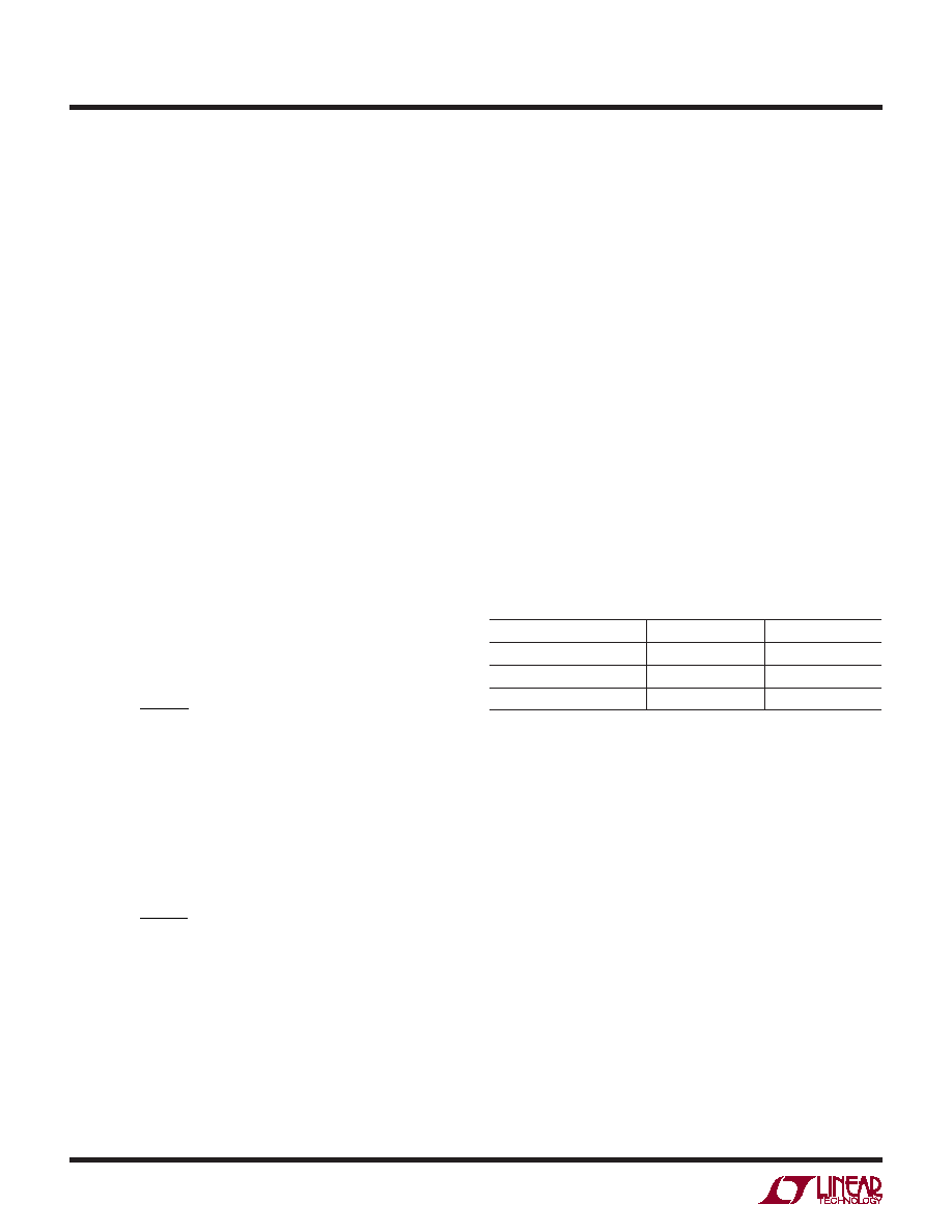
Table 2 illustrates the possible states of the CHRG and
FAULT pins when the battery charger is active.
Table 2. Charge Status Readings Using the CHRG and FAULT Pins
STATUS
CHRG
FAULT
Charging/NTC Fault
Low
High
Not Charging
High
Bad Battery
High
Low
An NTC fault pauses charging while the battery tempera-
ture is out of range but is not indicated using the CHRG
or FAULT pins.
If a battery is found to be unresponsive to charging (i.e.,
its voltage remains below 2.85V for 1/2 hour) the CHRG
pin goes high and the FAULT pin goes low to indicate a
bad battery fault.
Note that the LTC4160/LTC4160-1 are 3-terminal
PowerPath products where system load is always priori-
tized over battery charging. Due to excessive system load,
there may not be sufficient power to charge the battery
beyond the trickle charge threshold voltage within the bad
battery timeout period. In this case, the battery charger
will falsely indicate a bad battery. System software may
then reduce the load and reset the battery charger to try
again.
The FAULT pin is also used to indicate whether there is
a short circuit condition on VBUS when the bidirectional
OPERATION
相关PDF资料 |
PDF描述 |
|---|---|
| LM385BZ-1.2X | 1-OUTPUT TWO TERM VOLTAGE REFERENCE, 1.235 V, PBCY3 |
| LES008ZD28N | 1-OUTPUT 15 W DC-DC REG PWR SUPPLY MODULE |
| LFD150S | 1-OUTPUT 50 W DC-DC REG PWR SUPPLY MODULE |
| LT3575EFE#TRPBF | 4.2 A SWITCHING REGULATOR, 1000 kHz SWITCHING FREQ-MAX, PDSO16 |
| LM9140BXM-5.0 | 1-OUTPUT TWO TERM VOLTAGE REFERENCE, 5 V, PDSO8 |
相关代理商/技术参数 |
参数描述 |
|---|---|
| LTC4210 | 制造商:LINER 制造商全称:Linear Technology 功能描述:Dual Supply Hot Swap Controller for Advanced Mezzanine Card |
| LTC4210-1 | 制造商:LINER 制造商全称:Linear Technology 功能描述:Hot Swap Controller in 6-Lead SOT-23 Package |
| LTC42101CS6 | 制造商:Linear Technology 功能描述: |
| LTC4210-1CS6 | 制造商:Linear Technology 功能描述:Hot Swap Controller 1-CH 16.5V 6-Pin TSOT-23 |
| LTC4210-1CS6#PBF | 制造商:Linear Technology 功能描述:Hot Swap Controller 1-CH 16.5V 6-Pin TSOT-23 制造商:Linear Technology 功能描述:IC HOT SWAP CONT 制造商:Linear Technology 功能描述:HOT SWAP CNTRL 16.5VIN 6SOT23 制造商:Linear Technology 功能描述:HOT SWAP, CNTRL, 16.5VIN, 6SOT23 制造商:Linear Technology 功能描述:IC, HOT SWAP CONT; Controller Applications:Hot Board Insertion, Electronic Circuit Breaker, Industrial High Side Switch; Input Voltage:16.5V; Internal Switch:Yes; Supply Voltage Min:2.7V; Supply Voltage Max:16.5V; No. of Pins:6 ;RoHS Compliant: Yes |
发布紧急采购,3分钟左右您将得到回复。