- 您现在的位置:买卖IC网 > PDF目录79689 > LTC4160EUDC#TRPBF (LINEAR TECHNOLOGY CORP) POWER SUPPLY MANAGEMENT CKT, PQCC20 PDF资料下载
参数资料
| 型号: | LTC4160EUDC#TRPBF |
| 厂商: | LINEAR TECHNOLOGY CORP |
| 元件分类: | 电源管理 |
| 英文描述: | POWER SUPPLY MANAGEMENT CKT, PQCC20 |
| 封装: | 3 X 4 MM, 0.75 MM HEIGHT, LEAD FREE, PLASTIC, QFN-20 |
| 文件页数: | 14/32页 |
| 文件大小: | 422K |
| 代理商: | LTC4160EUDC#TRPBF |
第1页第2页第3页第4页第5页第6页第7页第8页第9页第10页第11页第12页第13页当前第14页第15页第16页第17页第18页第19页第20页第21页第22页第23页第24页第25页第26页第27页第28页第29页第30页第31页第32页
LTC4160/LTC4160-1
21
41601fa
APPLICATIONS INFORMATION
Bidirectional PowerPath Switching Regulator CLPROG
Resistor and Capacitor Selection
As described in the Bidirectional PowerPath Switching
Regulator – Step-Down Mode section, the resistor on the
CLPROG pin determines the average VBUS input current
limit. In step-down mode the switching regulator’s VBUS
input current limit can be set to either the 1x mode (USB
100mA), the 5x mode (USB 500mA) or the 10x mode. The
VBUS input current will be comprised of two components,
the current that is used to drive VOUT and the quiescent
current of the switching regulator. To ensure that the total
averageinputcurrentremainsbelowtheUSBspecification,
both components of input current should be considered.
The Electrical Characteristics table gives the typical values
for quiescent currents in all settings as well as current limit
programming accuracy. To get as close to the 500mA or
100mA specifications as possible, a precision resistor
should be used. Recall that:
IVBUS = IVBUSQ + VCLPROG/RCLPPROG (hCLPROG +1).
An averaging capacitor is required in parallel with the
resistor so that the switching regulator can determine the
average input current. This capacitor also provides the
dominant pole for the feedback loop when current limit
is reached. To ensure stability, the capacitor on CLPROG
should be 0.1F or larger.
Bidirectional PowerPath Switching Regulator Inductor
Selection
Because the VBUS voltage range and VOUT voltage range
of the PowerPath switching regulator are both fairly nar-
row, the LTC4160/LTC4160-1 were designed for a specific
inductance value of 3.3μH. Some inductors which may be
suitable for this application are listed in Table 3.
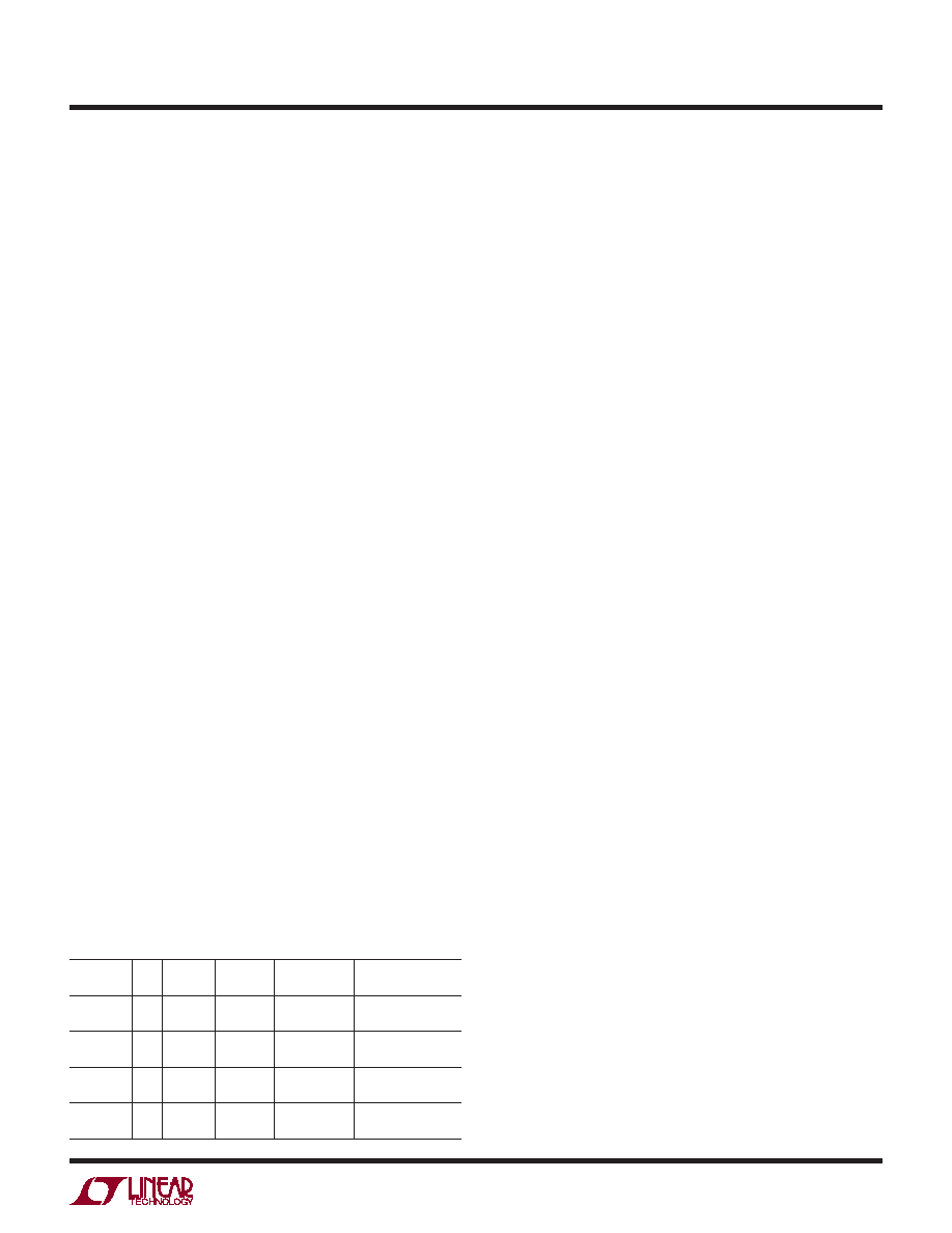
Table 3. Recommended PowerPath Inductors for the
LTC4160/LTC4160-1
INDUCTOR
TYPE
L
(μH)
MAX IDC
(A)
MAX DCR
(Ω)
SIZE IN mm
(L x W x H) MANUFACTURER
LPS4018
3.3
2.2
0.08
3.9 x 3.9 x 1.7 Coilcraft
www.coilcraft.com
D53LC
DB318C
3.3
2.26
1.55
0.034
0.070
5 x 5 x 3
3.8 x 3.8 x 1.8
Toko
www.toko.com
WE-TPC
Type M1
3.3
1.95
0.065
4.8 x 4.8 x 1.8 Wurth Electronik
www.we-online.com
CDRH6D12
CDRH6D38
3.3
2.2
3.5
0.063
0.020
6.7 x 6.7 x 1.5
7 x 7 x 4
Sumida
www.sumida.com
Bidirectional PowerPath Switching Regulator VBUS
and VOUT Bypass Capacitor Selection
The type and value of capacitors used with the LTC4160/
LTC4160-1 determine several important parameters such
as regulator control-loop stability and input voltage ripple.
Because the LTC4160/LTC4160-1 use a bidirectional
switching regulator between VBUS and VOUT, the VBUS
current waveform contains high frequency components.
It is strongly recommended that a low equivalent series
resistance (ESR) multilayer ceramic capacitor (MLCC) be
used to bypass VBUS. Tantalum and aluminum capacitors
arenotrecommendedbecauseoftheirhighESR.Thevalue
of the capacitor on VBUS directly controls the amount of
input ripple for a given load current. Increasing the size
of this capacitor will reduce the input ripple.
The inrush current limit specification for USB devices is
calculatedintermsofthetotalnumberofCoulombsneeded
to charge the VBUS bypass capacitor to 5V. The maximum
inrush charge for USB On-The-Go devices is 33μC. This
places a limit of 6.5μF of capacitance on VBUS assuming
a linear capacitor. However, most ceramic capacitors have
a capacitance that varies with bias voltage. The average
capacitanceneedstobelessthan6.5μFovera0Vto5Vbias
voltagerangetomeettheinrushcurrent-limitspecification.
A 10μF capacitor in a 0805 package, such as the Murata
GRM21BR71A106KE51L would be a suitable VBUSbypass
capacitor. If more capacitance is required for better noise
performance and stability, it should be connected directly
to the VBUS pin when using the overvoltage protection
circuit. This extra capacitance will be soft-connected over
a couple of milliseconds to limit inrush current and avoid
excessive transient voltage drops on VBUS.
To prevent large VOUT voltage steps during transient load
conditions, it is also recommended that an MLCC be used
to bypass VOUT. The output capacitor is used in the com-
pensation of the switching regulator. At least 10F with
low ESR are required on VOUT. Additional capacitance will
improve load transient performance and stability.
MLCCs typically have exceptional ESR performance.
MLCCscombinedwithatightboardlayoutandanunbroken
ground plane will yield very good performance and low
EMI emissions.
相关PDF资料 |
PDF描述 |
|---|---|
| LM385BZ-1.2X | 1-OUTPUT TWO TERM VOLTAGE REFERENCE, 1.235 V, PBCY3 |
| LES008ZD28N | 1-OUTPUT 15 W DC-DC REG PWR SUPPLY MODULE |
| LFD150S | 1-OUTPUT 50 W DC-DC REG PWR SUPPLY MODULE |
| LT3575EFE#TRPBF | 4.2 A SWITCHING REGULATOR, 1000 kHz SWITCHING FREQ-MAX, PDSO16 |
| LM9140BXM-5.0 | 1-OUTPUT TWO TERM VOLTAGE REFERENCE, 5 V, PDSO8 |
相关代理商/技术参数 |
参数描述 |
|---|---|
| LTC4210 | 制造商:LINER 制造商全称:Linear Technology 功能描述:Dual Supply Hot Swap Controller for Advanced Mezzanine Card |
| LTC4210-1 | 制造商:LINER 制造商全称:Linear Technology 功能描述:Hot Swap Controller in 6-Lead SOT-23 Package |
| LTC42101CS6 | 制造商:Linear Technology 功能描述: |
| LTC4210-1CS6 | 制造商:Linear Technology 功能描述:Hot Swap Controller 1-CH 16.5V 6-Pin TSOT-23 |
| LTC4210-1CS6#PBF | 制造商:Linear Technology 功能描述:Hot Swap Controller 1-CH 16.5V 6-Pin TSOT-23 制造商:Linear Technology 功能描述:IC HOT SWAP CONT 制造商:Linear Technology 功能描述:HOT SWAP CNTRL 16.5VIN 6SOT23 制造商:Linear Technology 功能描述:HOT SWAP, CNTRL, 16.5VIN, 6SOT23 制造商:Linear Technology 功能描述:IC, HOT SWAP CONT; Controller Applications:Hot Board Insertion, Electronic Circuit Breaker, Industrial High Side Switch; Input Voltage:16.5V; Internal Switch:Yes; Supply Voltage Min:2.7V; Supply Voltage Max:16.5V; No. of Pins:6 ;RoHS Compliant: Yes |
发布紧急采购,3分钟左右您将得到回复。