参数资料
| 型号: | LTC6403IUD-1#PBF |
| 厂商: | Linear Technology |
| 文件页数: | 16/20页 |
| 文件大小: | 0K |
| 描述: | IC AMP/DRIVER LN LP 16-QFN |
| 标准包装: | 121 |
| 类型: | ADC 驱动器 |
| 应用: | 数据采集 |
| 安装类型: | 表面贴装 |
| 封装/外壳: | 16-WFQFN 裸露焊盘 |
| 供应商设备封装: | 16-QFN-EP(3x3) |
| 包装: | 管件 |
| 产品目录页面: | 1323 (CN2011-ZH PDF) |
LTC6403-1
5
64031fa
Note 1: Stresses beyond those listed under Absolute Maximum Ratings
may cause permanent damage to the device. Exposure to any Absolute
Maximum Rating condition for extended periods may affect device
reliability and lifetime.
Note 2: The inputs +IN, –IN are protected by a pair of back-to-back diodes.
If the differential input voltage exceeds 1.4V, the input current should be
limited to less than 10mA. Input pins (+IN, –IN, VOCM, and SHDN) are also
protected by steering diodes to either supply. If the inputs should exceed
either supply voltage, the input current should be limited to less than
10mA.
Note 3: A heat sink may be required to keep the junction temperature
below the absolute maximum rating when the output is shorted
indenitely. Long term application of output currents in excess of the
absolute maximum ratings may impair the life of the device.
Note 4: The LTC6403-1 is guaranteed functional over the operating
temperature range –40°C to 85°C.
Note 5: The LTC6403C-1 is guaranteed to meet specied performance
from 0°C to 70°C. The LTC6403C-1 is designed, characterized, and
expected to meet specied performance from –40°C to 85°C but is
not tested or QA sampled at these temperatures. The LTC6403I-1 is
guaranteed to meet specied performance from –40°C to 85°C.
Note 6: Input bias current is dened as the average of the input currents
owing into Pin 6 and Pin 15 (–IN, and +IN). Input offset current is dened
as the difference of the input currents owing into Pin 15 and Pin 6 (IOS =
IB+ – IB–)
Note 7: Input common mode range is tested using the test circuit of
Figure 1 by measuring the differential gain with a ±1V differential output
with VICM = mid-supply, and also with VICM at the input common mode
range limits listed in the Electrical Characteristics table, verifying that the
differential gain has not deviated from the mid supply common mode input
case by more than 1%, and the common mode offset (VOSCM) has not
deviated from the mid-supply case by more than ±10mV.
The voltage range for the output common mode range is tested using the
test circuit of Figure 1 by applying a voltage on the VOCM pin and testing at
both mid supply and at the Electrical Characteristics table limits to verify
that the differential gain has not deviated from the mid supply VOCM case
by more than 1%, and the common mode offset (VOSCM) has not deviated
by more than ±10mV from the mid supply case.
Note 8: Input CMRR is dened as the ratio of the change in the input
common mode voltage at the pins +IN or –IN to the change in differential
input referred voltage offset. Output CMRR is dened as the ratio of the
change in the voltage at the VOCM pin to the change in differential input
referred voltage offset. These specications are strongly dependent on
feedback ratio matching between the two outputs and their respective
inputs, and it is difcult to measure actual amplier performance. See The
Effects of Resistor Pair Mismatch in the Applications Information section
of this datasheet. For a better indicator of actual amplier performance
independent of feedback component matching, refer to the PSRR
specication.
Note 9: Differential power supply rejection (PSRR) is dened as the ratio
of the change in supply voltage to the change in differential input referred
voltage offset. Common mode power supply rejection (PSRRCM) is
dened as the ratio of the change in supply voltage to the change in the
common mode offset, VOUTCM – VOCM.
Note 10: Output swings are measured as differences between the output
and the respective power supply rail.
Note 11: Extended operation with the output shorted may cause junction
temperatures to exceed the 150°C limit and is not recommended. See Note
3 for more details.
Note 12: A resistive load is not required when driving an AD converter with
the LTC6403-1. Therefore, typical output power is very small. In order to
compare the LTC6403-1 with ampliers that require 50
Ω output load, the
LTC6403-1 output voltage swing driving a given RL is converted to OIP3 as
if it were driving a 50
Ω load. Using this modied convention, 2VP-P is by
denition equal to 10dBm, regardless of actual RL.
The
l denotes the specications which apply
over the full operating temperature range, otherwise specications are at TA = 25°C, V+ = 3V, V– = 0V, VCM = VOCM = VICM = Mid-Supply,
VSHDN = OPEN, RI = 402Ω, RF = 402Ω, RT = 25.5Ω, unless otherwise noted (See Figure 2). VS is dened (V+ – V–). VOUTCM is dened
as (V+OUT + V–OUT)/2. VICM is dened as (V+IN + V–IN)/2. VOUTDIFF is dened as (V+OUT – V–OUT). VINDIFF is dened as (VINP – VINM).
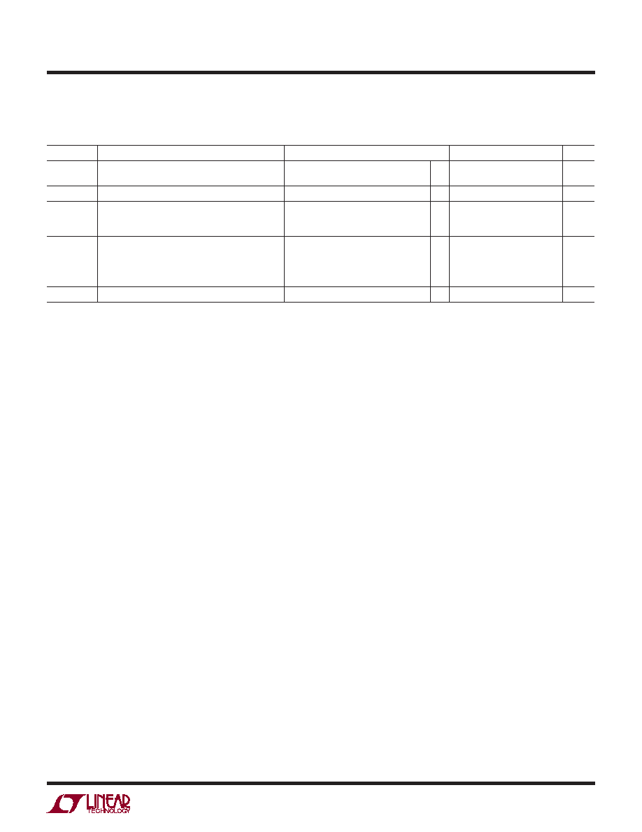
LTC6403-1 AC ELECTRICAL CHARACTERISTICS
SYMBOL
PARAMETER
CONDITIONS
MIN
TYP
MAX
UNITS
IMD
Third-Order IMD at 10MHz
f1 = 9.5MHz, f2 = 10.5MHz
VS = 3V, VOUTDIFF = 2VP-P Envelope
–72
dBc
OIP3
Equivalent OIP3 at 3MHz (Note 12)
VS = 3V
48
dBm
tS
Settling Time
2V Step at Output
VS = 3V, Single-Ended Input
1% Settling
0.1% Settling
20
30
ns
NF
Noise Figure, f = 3MHz
RSOURCE = 804Ω, RI = 402Ω,
RF = 402Ω, VS = 3V
RSOURCE = 200Ω, RI = 100Ω,
RF = 402Ω, VS = 3V
10.8
8.9
dB
f3dBFILTER
Differential Filter 3dB Bandwidth
44.2
MHz
相关PDF资料 |
PDF描述 |
|---|---|
| AD9744ARURL7 | IC DAC 14BIT 210MSPS 28-TSSOP |
| LT6109HMS-2#PBF | IC AMP CURRENT SENSE 10-MSOP |
| LTC6403CUD-1#PBF | IC AMP/DRIVER LN LP 16-QFN |
| 74AHC1G14GV,125 | IC SCHMITT-TRG INV GATE SOT-753 |
| 74HC1G00GV,125 | IC 2-INPUT NAND GATE SC-74A |
相关代理商/技术参数 |
参数描述 |
|---|---|
| LTC6403IUD-1-TRPBF | 制造商:LINER 制造商全称:Linear Technology 功能描述:200MHz, Low Noise, Low Power Fully Differential Input/Output Amplifi er/Driver |
| LTC6404 | 制造商:LINER 制造商全称:Linear Technology 功能描述:600MHz, Low Noise, High Precision Fully Differential Input/Output Amplifi er/Driver |
| LTC6404-1 | 制造商:LINER 制造商全称:Linear Technology 功能描述:16-Bit, 20Msps ADC |
| LTC6404-2 | 制造商:LINER 制造商全称:Linear Technology 功能描述:2.7GHz, 5V, Low Noise,Rail-to-Rail Input Differential Amplifier/Driver |
| LTC6404-4 | 制造商:LINER 制造商全称:Linear Technology 功能描述:2.7GHz, 5V, Low Noise,Rail-to-Rail Input Differential Amplifier/Driver |
发布紧急采购,3分钟左右您将得到回复。