- 您现在的位置:买卖IC网 > PDF目录1935 > LTC6605IDJC-14#TRPBF (Linear Technology)IC FILTER 14MHZ DUAL 22-DFN PDF资料下载
参数资料
| 型号: | LTC6605IDJC-14#TRPBF |
| 厂商: | Linear Technology |
| 文件页数: | 15/20页 |
| 文件大小: | 0K |
| 描述: | IC FILTER 14MHZ DUAL 22-DFN |
| 标准包装: | 2,500 |
| 滤波器类型: | 抗混迭 |
| 频率 - 截止或中心: | 5MHz |
| 滤波器数: | 2 |
| 滤波器阶数: | 2nd |
| 电源电压: | 2.7 V ~ 5.25 V |
| 安装类型: | 表面贴装 |
| 封装/外壳: | 22-WFDFN 裸露焊盘 |
| 供应商设备封装: | 22-DFN(6x3)裸露焊盘 |
| 包装: | 带卷 (TR) |
LTC6605-14
4
660514f
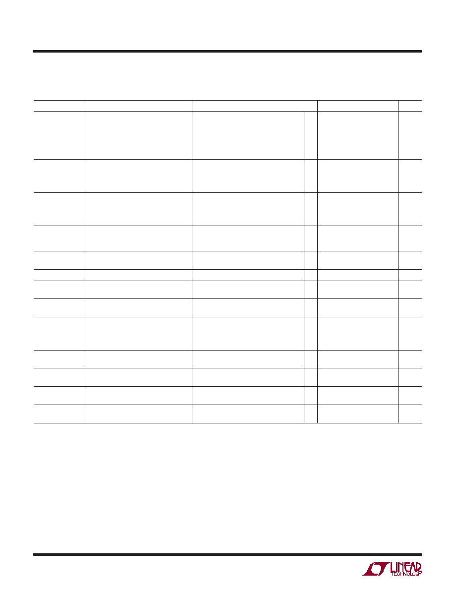
AC ELECTRICAL CHARACTERISTICS The l denotes the specications which apply over the full operating
temperature range, otherwise specications are at TA = 25°C. V+ = 3V, V– = 0V, VINCM = VOCM = mid-supply, VBIAS = V+, unless
otherwise noted. Filter congured as in Figure 2, unless otherwise noted. VS is dened as (V+ – V–). VOUTCM is dened as (V+OUT +
V–OUT)/2. VINCM is dened as (V+IN + V–IN)/2. VOUTDIFF is dened as (V+OUT – V–OUT). VINDIFF is dened as (V+IN + V–IN).
Note 1: Stresses beyond those listed under Absolute Maximum Ratings
may cause permanent damage to the device. Exposure to any Absolute
Maximum Rating condition for extended periods may affect device
reliability and lifetime.
Note 2: All pins are protected by steering diodes to either supply. If any
pin is driven beyond the LTC6605-14’s supply voltage, the excess input
current (current in excess of what it takes to drive that pin to the supply
rail) should be limited to less than 10mA.
Note 3: A heat sink may be required to keep the junction temperature
below the Absolute Maximum Rating when the output is shorted
indenitely. Long-term application of output currents in excess of the
Absolute Maximum Ratings may impair the life of the device.
Note 4: Both the LTC6605C and the LTC6605I are guaranteed functional
over the operating temperature range –40°C to 85°C.
Note 5: The LTC6605C is guaranteed to meet specied performance
from 0°C to 70°C. The LTC6605C is designed, characterized and
expected to meet specied performance from –40°C to 85°C, but is
not tested or QA sampled at these temperatures. The LTC6605I is
guaranteed to meet specied performance from –40°C to 85°C.
Note 6: Output referred voltage offset is a function of gain. To determine
output referred voltage offset, or output voltage offset drift, multiply VOS
by the noise gain (1 + GAIN). See Figure 3.
Note 7: Input bias current is dened as the average of the currents
owing into the noninverting and inverting inputs of the internal amplier
and is calculated from measurements made at the pins of the IC. Input
offset current is dened as the difference of the currents owing into
the noninverting and inverting inputs of the internal amplier and is
calculated from measurements made at the pins of the IC.
SYMBOL
PARAMETER
CONDITIONS
MIN
TYP
MAX
UNITS
Gain
Filter Gain
ΔVIN = ±0.125V, DC
VINDIFF = 0.5VP-P, f = 7MHz
VINDIFF = 0.5VP-P, f = 10.5MHz
VINDIFF = 0.5VP-P, f = 14MHz
VINDIFF = 0.5VP-P, f = 28MHz
VINDIFF = 0.5VP-P, f = 70MHz
l
–0.25
–1.25
–2.5
–4.15
–11.65
–28
±0.05
–0.92
–2.12
–3.75
–11.1
–25.2
0.25
–0.6
–1.75
–3.35
–10.6
–24.3
dB
Phase
Filter Phase
ΔVIN = ±0.125V, DC
VINDIFF = 0.5VP-P, f = 7MHz
VINDIFF = 0.5VP-P, f = 10.5MHz
VINDIFF = 0.5VP-P, f = 14MHz
0
–43.3
–63.6
–81.2
Deg
ΔGain
Gain Match (Channel-to-Channel)
ΔVIN = ±0.125V, DC
VINDIFF = 0.5VP-P, f = 7MHz
VINDIFF = 0.5VP-P, f = 10.5MHz
VINDIFF = 0.5VP-P, f = 14MHz
l
–0.175
–0.2
–0.25
±0.04
±0.05
0.175
0.2
0.25
dB
ΔPhase
Phase Match (Channel-to-Channel)
VINDIFF = 0.5VP-P, f = 7MHz
VINDIFF = 0.5VP-P, f = 10.5MHz
VINDIFF = 0.5VP-P, f = 14MHz
l
–0.9
–1.0
–1.1
±0.2
0.9
1.0
1.1
Deg
2V/V Gain
Filter Gain in 2V/V Conguration
Inputs at ±IN1 Pins, ±IN2 Pins Floating
ΔVIN = ±0.125V, DC
l
5.8
6
6.25
dB
Channel Separation
VINDIFF = 1VP-P, f = 7MHz
–96
dB
fO TC
Filter Cut-Off Frequency Temperature
Coefcient (T = –45°C to 85°C)
BIAS = V+
BIAS = Floating
–95
–230
ppm/°C
Noise
Integrated Output Noise
(BW = 10kHz to 28MHz)
54
μVRMS
Input Referred Noise Density
(f = 1MHz)
BIAS = V+
Figure 4, Gain = 1
Figure 4, Gain = 2
Figure 4, Gain = 3
13.2
6.6
4.4
nV/√Hz
en
Voltage Noise Density Referred to
Op Amp Inputs (f = 1MHz)
BIAS = V+
BIAS = Floating
2.1
2.6
nV/√Hz
in
Current Noise Density Referred to
Op Amp Inputs (f = 1MHz)
BIAS = V+
BIAS = Floating
3
2.1
pA/√Hz
HD2
2nd Harmonic Distortion
fIN = 7MHz; VIN = 2VP-P Single-Ended
BIAS = V+
BIAS = Floating, RLOAD = 400Ω
–81
–69
dBc
HD3
3rd Harmonic Distortion
fIN = 7MHz; VIN = 2VP-P Single-Ended
BIAS = V+
BIAS = Floating, RLOAD = 400Ω
–93
–76
dBc
相关PDF资料 |
PDF描述 |
|---|---|
| LTC6605IDJC-7#TRPBF | IC FILTER 7MHZ DUAL 22-DFN |
| LTK001ACN8 | IC THERMOCOUPL COMP& KIT 8DIP |
| LX64EV-5FN100I | IC SWITCH DIGITAL 100FPBGA |
| M-991 | IC GENERATOR TONE LP CMOS 14-DIP |
| M1A3P1000L-1FGG484I | IC FPGA M1 1KB FLASH 1M 484FBGA |
相关代理商/技术参数 |
参数描述 |
|---|---|
| LTC6605IDJC-7#PBF | 功能描述:IC FILTER 7MHZ DUAL 22-DFN RoHS:是 类别:集成电路 (IC) >> 接口 - 滤波器 - 有源 系列:- 产品培训模块:Lead (SnPb) Finish for COTS Obsolescence Mitigation Program 标准包装:1,000 系列:- 滤波器类型:连续时间,带通低通 频率 - 截止或中心:150kHz 滤波器数:4 滤波器阶数:8th 电源电压:4.74 V ~ 11 V,±2.37 V ~ 5.5 V 安装类型:表面贴装 封装/外壳:28-SOIC(0.295",7.50mm 宽) 供应商设备封装:28-SOIC W 包装:带卷 (TR) |
| LTC6605IDJC-7#TRPBF | 功能描述:IC FILTER 7MHZ DUAL 22-DFN RoHS:是 类别:集成电路 (IC) >> 接口 - 滤波器 - 有源 系列:- 产品培训模块:Lead (SnPb) Finish for COTS Obsolescence Mitigation Program 标准包装:1,000 系列:- 滤波器类型:连续时间,带通低通 频率 - 截止或中心:150kHz 滤波器数:4 滤波器阶数:8th 电源电压:4.74 V ~ 11 V,±2.37 V ~ 5.5 V 安装类型:表面贴装 封装/外壳:28-SOIC(0.295",7.50mm 宽) 供应商设备封装:28-SOIC W 包装:带卷 (TR) |
| LTC6605IDJC-7-PBF | 制造商:LINER 制造商全称:Linear Technology 功能描述:Dual Matched 7MHz Filter with Low Noise, Low Distortion Differential Amplifi er |
| LTC6605IDJC-7-TRPBF | 制造商:LINER 制造商全称:Linear Technology 功能描述:Dual Matched 7MHz Filter with Low Noise, Low Distortion Differential Amplifi er |
| LTC660CN8 | 功能描述:IC REG DBL INV ADJ 0.1A 8DIP RoHS:否 类别:集成电路 (IC) >> PMIC - 稳压器 - DC DC 开关稳压器 系列:- 标准包装:2,500 系列:- 类型:升压(升压) 输出类型:可调式 输出数:1 输出电压:1.24 V ~ 30 V 输入电压:1.5 V ~ 12 V PWM 型:电流模式,混合 频率 - 开关:600kHz 电流 - 输出:500mA 同步整流器:无 工作温度:-40°C ~ 85°C 安装类型:表面贴装 封装/外壳:8-SOIC(0.154",3.90mm 宽) 包装:带卷 (TR) 供应商设备封装:8-SOIC |
发布紧急采购,3分钟左右您将得到回复。