- 您现在的位置:买卖IC网 > PDF目录45029 > M37161MF-XXXSP 8-BIT, MROM, 8 MHz, MICROCONTROLLER, PDIP42 PDF资料下载
参数资料
| 型号: | M37161MF-XXXSP |
| 元件分类: | 微控制器/微处理器 |
| 英文描述: | 8-BIT, MROM, 8 MHz, MICROCONTROLLER, PDIP42 |
| 封装: | 0.600 INCH, 1.78 MM PITCH, PLASTIC, SDIP-42 |
| 文件页数: | 116/129页 |
| 文件大小: | 1092K |
| 代理商: | M37161MF-XXXSP |
第1页第2页第3页第4页第5页第6页第7页第8页第9页第10页第11页第12页第13页第14页第15页第16页第17页第18页第19页第20页第21页第22页第23页第24页第25页第26页第27页第28页第29页第30页第31页第32页第33页第34页第35页第36页第37页第38页第39页第40页第41页第42页第43页第44页第45页第46页第47页第48页第49页第50页第51页第52页第53页第54页第55页第56页第57页第58页第59页第60页第61页第62页第63页第64页第65页第66页第67页第68页第69页第70页第71页第72页第73页第74页第75页第76页第77页第78页第79页第80页第81页第82页第83页第84页第85页第86页第87页第88页第89页第90页第91页第92页第93页第94页第95页第96页第97页第98页第99页第100页第101页第102页第103页第104页第105页第106页第107页第108页第109页第110页第111页第112页第113页第114页第115页当前第116页第117页第118页第119页第120页第121页第122页第123页第124页第125页第126页第127页第128页第129页
Rev.1.00
2003.11.25
page 87 of 128
M37161M8/MA/MF-XXXSP/FP,M37161EFSP/FP
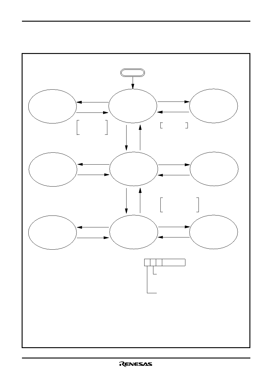
Fig.8.13.6 State Transitions of System Clock
Reset
The example assumes that 8 MHz is being applied to the XIN pin and 32 kHz to the XCIN pin. The
φ indicates the internal clock.
WIT instruction
CM7 : Internal system clock selection bit
0 : XIN-XOUT selected (high-speed mode)
1 : XCIN-XCOUT selected (low-speed mode)
CPU mode register
(Address : 00FB16)
CM6 : Main clock (XIN–XOUT) stop bit
0 : Oscillating
1 : Stopped
8 MHz oscillating
32 kHz oscillating
φ is stopped (“H”)
Timer operating
8 MHz oscillating
32 kHz oscillating
f(
φ) = 4 MHz
8 MHz stopped
32 kHz stopped
φ is stopped (“H”)
8 MHz oscillating
32 kHz oscillating
φ is stopped (“H”)
Timer operating
(See note 3)
8 MHz oscillating
32 kHz oscillating
f(
φ) = 16kHz
8 MHz stopped
32 kHz stopped
φ is stopped (“H”)
8 MHz stopped
32 kHz stopped
φ = stopped (“H”)
8 MHz stopped
32 kHz oscillating
f(
φ) = 16 kHz
8 MHz stopped
32 kHz oscillating
φ is stopped (“H”)
Timer operating
(See note 3)
Interrupt
STP instruction
Interrupt (See note 1)
WIT instruction
Interrupt
WIT instruction
Interrupt
STP instruction
Interrupt (See note 2)
STP instruction
Interrupt (See note 2)
CM7 = 1
CM7 = 0
CM6 = 1
CM6 = 0
External INT,
timer interrupt,
or SI/O interrupt
External INT
Notes 1: When the STP state is ended, a delay of approximately 8 ms is automatically generated by timer 3 and timer 4.
2: The delay after the STP state ends is approximately 2s.
3: When the internal clock
φ divided by 8 is used as the timer count source, the frequency of the count source is 2 kHz.
The program must
allow time for 8 MHz
oscillation to stabilize
High-speed operation start
mode
相关PDF资料 |
PDF描述 |
|---|---|
| M37161EFSP | 8-BIT, OTPROM, 8 MHz, MICROCONTROLLER, PDIP42 |
| M37161MA-XXXSP | 8-BIT, MROM, 8 MHz, MICROCONTROLLER, PDIP42 |
| M37161M8-XXXSP | 8-BIT, MROM, 8 MHz, MICROCONTROLLER, PDIP42 |
| M37202E3SP | 8-BIT, OTPROM, 4 MHz, MICROCONTROLLER, PDIP64 |
| M37207EFFP | 8-BIT, OTPROM, 8.1 MHz, MICROCONTROLLER, PQFP80 |
相关代理商/技术参数 |
参数描述 |
|---|---|
| M3720 | 制造商:未知厂家 制造商全称:未知厂家 功能描述:1 KEY 1 SOUND |
| M3720-1 | 制造商:未知厂家 制造商全称:未知厂家 功能描述:1 KEY 1 SOUND |
| M3720-10 | 制造商:未知厂家 制造商全称:未知厂家 功能描述:1 KEY 1 SOUND |
| M3720-2 | 制造商:未知厂家 制造商全称:未知厂家 功能描述:1 KEY 1 SOUND |
| M3720-3 | 制造商:未知厂家 制造商全称:未知厂家 功能描述:1 KEY 1 SOUND |
发布紧急采购,3分钟左右您将得到回复。