- 您现在的位置:买卖IC网 > PDF目录80570 > M38513M4-XXXFP 8-BIT, MROM, 4 MHz, MICROCONTROLLER, PDSO42 PDF资料下载
参数资料
| 型号: | M38513M4-XXXFP |
| 元件分类: | 微控制器/微处理器 |
| 英文描述: | 8-BIT, MROM, 4 MHz, MICROCONTROLLER, PDSO42 |
| 封装: | 0.450 INCH, PLASTIC, SSOP-42 |
| 文件页数: | 47/91页 |
| 文件大小: | 1295K |
| 代理商: | M38513M4-XXXFP |
第1页第2页第3页第4页第5页第6页第7页第8页第9页第10页第11页第12页第13页第14页第15页第16页第17页第18页第19页第20页第21页第22页第23页第24页第25页第26页第27页第28页第29页第30页第31页第32页第33页第34页第35页第36页第37页第38页第39页第40页第41页第42页第43页第44页第45页第46页当前第47页第48页第49页第50页第51页第52页第53页第54页第55页第56页第57页第58页第59页第60页第61页第62页第63页第64页第65页第66页第67页第68页第69页第70页第71页第72页第73页第74页第75页第76页第77页第78页第79页第80页第81页第82页第83页第84页第85页第86页第87页第88页第89页第90页第91页
51
SINGLE-CHIP 8-BIT CMOS MICROCOMPUTER
MITSUBISHI MICROCOMPUTERS
3851 Group
(Built-in 24 KB or more ROM)
Outline Performance (CPU Rewrite Mode)
CPU rewrite mode is usable in the single-chip or Boot mode. The
only User ROM area can be rewritten in CPU rewrite mode.
In CPU rewrite mode, the CPU erases, programs and reads the in-
ternal flash memory by executing software commands. This
rewrite control program must be transferred to the RAM before it
can be executed.
The MCU enters CPU rewrite mode by applying 5 V ± 0.5 V to the
CNVSS pin and setting “1” to the CPU Rewrite Mode Select Bit (bit
1 of address 0FFE16). Software commands are accepted once the
mode is entered.
Use software commands to control program and erase operations.
Whether a program or erase operation has terminated normally or
in error can be verified by reading the status register.
Figure 58 shows the flash memory control register.
Bit 0 is the RY/BY status flag used exclusively to read the operat-
ing status of the flash memory. During programming and erase
operations, it is “0” (busy). Otherwise, it is “1” (ready).
Bit 1 is the CPU Rewrite Mode Select Bit. When this bit is set to
“1”, the MCU enters CPU rewrite mode. Software commands are
accepted once the mode is entered. In CPU rewrite mode, the
CPU becomes unable to access the internal flash memory directly.
Therefore, use the control program in the RAM for write to bit 1. To
set this bit to “1”, it is necessary to write “0” and then write “1” in
succession. The bit can be set to “0” by only writing “0”.
Bit 2 is the CPU Rewrite Mode Entry Flag. This flag indicates “1” in
CPU rewrite mode, so that reading this flag can check whether
CPU rewrite mode has been entered or not.
Bit 3 is the flash memory reset bit used to reset the control circuit
of internal flash memory. This bit is used when exiting CPU rewrite
mode and when flash memory access has failed. When the CPU
Rewrite Mode Select Bit is “1”, setting “1” for this bit resets the
control circuit. To set this bit to “1”, it is necessary to write “0” and
then write “1” in succession. To release the reset, it is necessary
to set this bit to “0”.
Bit 4 is the User Area/Boot Area Select Bit. When this bit is set to
“1”, Boot ROM area is accessed, and CPU rewrite mode in Boot
ROM area is available. In Boot mode, this bit is set to “1” auto-
matically. Reprogramming of this bit must be in the RAM.
Figure 59 shows a flowchart for setting/releasing CPU rewrite
mode.
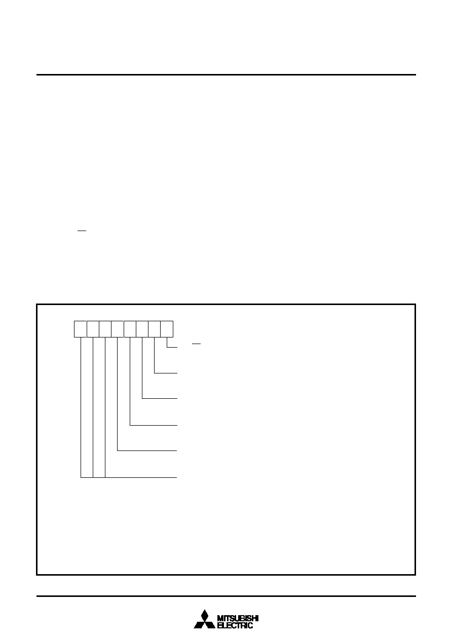
Fig. 58 Structure of flash memory control register
Flash memory control register (address 0FFE16) (Note 1)
FMCR
RY/BY status flag
0: Busy (being programmed or erased)
1: Ready
CPU rewrite mode select bit (Note 2)
0: Normal mode (Software commands invalid)
1: CPU rewrite mode (Software commands acceptable)
CPU rewrite mode entry flag
0: Normal mode
1: CPU rewrite mode
Flash memory reset bit (Note 3)
0: Normal operation
1: Reset
User ROM area / Boot ROM area select bit (Note 4)
0: User ROM area accessed
1: Boot ROM area accessed
Reserved bits (Indefinite at read/ “0” at write)
b0
b7
Notes1: The contents of flash memory control register are “XXX00001” just after reset release. In the mask
ROM version, this address is reserved area.
2: For this bit to be set to “1”, the user needs to write “0” and then “1” to it in succession. If it is not
this procedure, this bit will not be set to “1”. Additionally, it is required to ensure that no interrupt
will be generated during that interval.
Use the control program in the area except the built-in flash memory for write to this bit.
3: This bit is valid when the CPU rewrite mode select bit is “1”. Set this bit 3 to “0” subsequently after
setting bit 3 to “1”.
4: Use the control program in the area except the built-in flash memory for write to this bit.
相关PDF资料 |
PDF描述 |
|---|---|
| M30620SFP | 16-BIT, 16 MHz, MICROCONTROLLER, PQFP100 |
| MSU2051C16-YYYJ | 8-BIT, MROM, 16 MHz, MICROCONTROLLER, PQCC44 |
| MC68LK332GCFC16 | 32-BIT, 16.78 MHz, MICROCONTROLLER, PQFP132 |
| ML9203-XXGA | 16 X 35 DOTS FLUORESCENT DSPL CTRL, PQFP100 |
| M8813F2Y-15T1T | 128K X 8 FLASH, 27 I/O, PIA-GENERAL PURPOSE, PQFP52 |
相关代理商/技术参数 |
参数描述 |
|---|---|
| M38514E6FP | 制造商:Renesas Electronics Corporation 功能描述:SLIM740 OTP 24K/640B RAM, W/A-D, I2C, L - Rail/Tube |
| M38514E6SP | 制造商:Renesas Electronics Corporation 功能描述:SLIM740 OTP 24K/640B RAM, W/A-D, I2C, L - Rail/Tube |
| M38517T-ADS | 功能描述:DEV TMP TRGT BRD FOR M38517RSS & RoHS:否 类别:编程器,开发系统 >> 配件 系列:- 标准包装:1 系列:- 附件类型:适配器板 适用于相关产品:RCB230,RCB231,RCB212 配用:26790D-ND - RCB BREAKOUT BOARD RS232 CABLE |
| M38517T-PAC | 功能描述:DEV SIMPLE TOOL EMULATOR FOR M38 RoHS:否 类别:编程器,开发系统 >> 内电路编程器、仿真器以及调试器 系列:- 产品变化通告:Development Systems Discontinuation 19/Jul/2010 标准包装:1 系列:* 类型:* 适用于相关产品:* 所含物品:* |
| M3852 BK001 | 制造商:Alpha Wire 功能描述:CBL 8COND 14AWG BLK 1000' |
发布紧急采购,3分钟左右您将得到回复。