- 您现在的位置:买卖IC网 > PDF目录69016 > M41ST87YMX6TR (STMICROELECTRONICS) 1 TIMER(S), REAL TIME CLOCK, PDSO28 PDF资料下载
参数资料
| 型号: | M41ST87YMX6TR |
| 厂商: | STMICROELECTRONICS |
| 元件分类: | 时钟/数据恢复及定时提取 |
| 英文描述: | 1 TIMER(S), REAL TIME CLOCK, PDSO28 |
| 封装: | 0.300 INCH, ROHS COMPLIANT, PLASTIC, SOX-28 |
| 文件页数: | 30/48页 |
| 文件大小: | 457K |
| 代理商: | M41ST87YMX6TR |
第1页第2页第3页第4页第5页第6页第7页第8页第9页第10页第11页第12页第13页第14页第15页第16页第17页第18页第19页第20页第21页第22页第23页第24页第25页第26页第27页第28页第29页当前第30页第31页第32页第33页第34页第35页第36页第37页第38页第39页第40页第41页第42页第43页第44页第45页第46页第47页第48页
Clock operation
M41ST87Y, M41ST87W
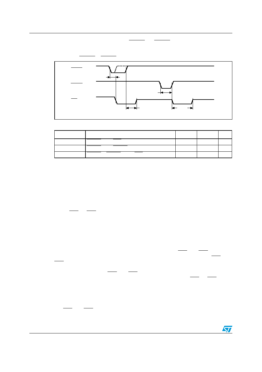
tR2 will not generate a reset condition. RSTIN1 and RSTIN2 are each internally pulled up to
VCC through a 100 kΩ resistor.
Figure 25.
RSTIN1 & RSTIN2 timing waveforms
Table 10.
Reset AC characteristics
3.9
Power-fail comparators (1 and 2)
Two power-fail inputs (PFI1 and PFI2) are compared to an internal reference voltage (1.25V).
If either PFI1 or PFI2 is less than the power-fail threshold (VPFI), the associated power-fail
output (PFO1 or PFO2) will go low. This function is intended for use as an under-voltage
detector to signal a failing power supply. Typically PFI1 and PFI2 are connected through
external voltage dividers (see Figure 4 on page 10) to either the unregulated DC input (if it is
available) or the regulated output of the VCC regulator. The voltage divider can be set up
such that the voltage at PFI1 or PFI2 falls below VPFI several milliseconds before the
regulated VCC input to the M41ST87Y/W or the microprocessor drops below the minimum
operating voltage.
During battery back-up, the power-fail comparator turns off and PFO1 and PFO2 go (or
remain) low. This occurs after VCC drops below VPFD(min). When power returns, PFO1 and
PFO2 are forced high, irrespective of VPFI for the write protect time (trec), which is the time
from VPFD(max) until the inputs are recognized. At the end of this time, the power-fail
comparator is enabled and PFO1 and PFO2 follow PFI1 and PFI2. If the comparator is
unused, PFI1 or PFI2 should be connected to VSS and the associated PFO1 or PFO2 left
unconnected.
3.10
Power-fail outputs
The PFO1 and PFO2 outputs are programmable as N-channel, open drain output drivers, or
full-CMOS output drivers. By setting the power-fail output open drain bit (PFOD) to a '1,' the
Symbol
Parameter(1)
1.
Valid for ambient operating temperature: TA = –40 to 85°C; VCC = 4.5 to 5.5 V or 2.7 to 3.6 V (except where
noted).
Min
Max
Unit
tR1
(2)
2.
Pulse widths of less than 100 ns will result in no RESET (for noise immunity).
RSTIN1 low to RST low (min pulse width)
100
200
ns
tR2
RSTIN2 low to RSTIN2 high (min pulse width)
100
200
ns
trec
(3)
3.
Programmable (see Table 12 on page 39). Same function as power-on reset.
RSTIN1 or RSTIN2 high to RST high
96
ms
AI07072
RSTIN1
RST
RSTIN2
tR1
trec
Hi-Z
tR2
trec
Hi-Z
相关PDF资料 |
PDF描述 |
|---|---|
| M41ST87WMX6TR | 1 TIMER(S), REAL TIME CLOCK, PDSO28 |
| M41ST95WMX6 | 1 TIMER(S), REAL TIME CLOCK, PDSO28 |
| M41ST95YMH6E | 1 TIMER(S), REAL TIME CLOCK, PDSO28 |
| M41ST95YMH6 | 1 TIMER(S), REAL TIME CLOCK, PDSO28 |
| M41ST95YMX6 | 1 TIMER(S), REAL TIME CLOCK, PDSO28 |
相关代理商/技术参数 |
参数描述 |
|---|---|
| M41ST87YSS6 | 制造商:STMICROELECTRONICS 制造商全称:STMicroelectronics 功能描述:5.0 V and 3.3/3.0 V secure serial RTC and NVRAM supervisor with tamper detection and 128 bytes of clearable NVRAM |
| M41ST87YSS6F | 制造商:STMICROELECTRONICS 制造商全称:STMicroelectronics 功能描述:5.0 V and 3.3/3.0 V secure serial RTC and NVRAM supervisor with tamper detection and 128 bytes of clearable NVRAM |
| M41ST95W | 制造商:STMICROELECTRONICS 制造商全称:STMicroelectronics 功能描述:5.0 or 3.0V, 512 bit (64 bit X 8) Serial RTC (SPI) SRAM and NVRAM Supervisor |
| M41ST95WMH6 | 制造商:STMICROELECTRONICS 制造商全称:STMicroelectronics 功能描述:5.0 or 3.0V, 512 bit (64 bit X 8) Serial RTC (SPI) SRAM and NVRAM Supervisor |
| M41ST95WMH6E | 制造商:STMICROELECTRONICS 制造商全称:STMicroelectronics 功能描述:5.0 or 3.0V, 512 bit (64 bit X 8) Serial RTC (SPI) SRAM and NVRAM Supervisor |
发布紧急采购,3分钟左右您将得到回复。