- 您现在的位置:买卖IC网 > PDF目录11817 > MAX14830ETM+T (Maxim Integrated Products)IC UART PDF资料下载
参数资料
| 型号: | MAX14830ETM+T |
| 厂商: | Maxim Integrated Products |
| 文件页数: | 54/68页 |
| 文件大小: | 0K |
| 描述: | IC UART |
| 产品培训模块: | Obsolescence Mitigation Program |
| 标准包装: | 2,500 |
| 系列: | * |
第1页第2页第3页第4页第5页第6页第7页第8页第9页第10页第11页第12页第13页第14页第15页第16页第17页第18页第19页第20页第21页第22页第23页第24页第25页第26页第27页第28页第29页第30页第31页第32页第33页第34页第35页第36页第37页第38页第39页第40页第41页第42页第43页第44页第45页第46页第47页第48页第49页第50页第51页第52页第53页当前第54页第55页第56页第57页第58页第59页第60页第61页第62页第63页第64页第65页第66页第67页第68页
58
Maxim Integrated
Quad Serial UART with 128-Word FIFOs
MAX14830
Serial Controller Interface
The MAX14830 can be controlled through SPI or I2C as
defined by the logic on SPI/I2C. See the Pin Configuration
section for further details.
SPI Interface
The SPI interface supports both single cycle and burst
read/write access. The SPI master must generate clock
and data signals in SPI MODE0 (i.e. with clock polarity
CPOL = 0 and clock phase CPHA = 0).
Each of the four UARTs is addressed using 2 bits (U1
and U0) in the command byte (see Tables 10 and 11).
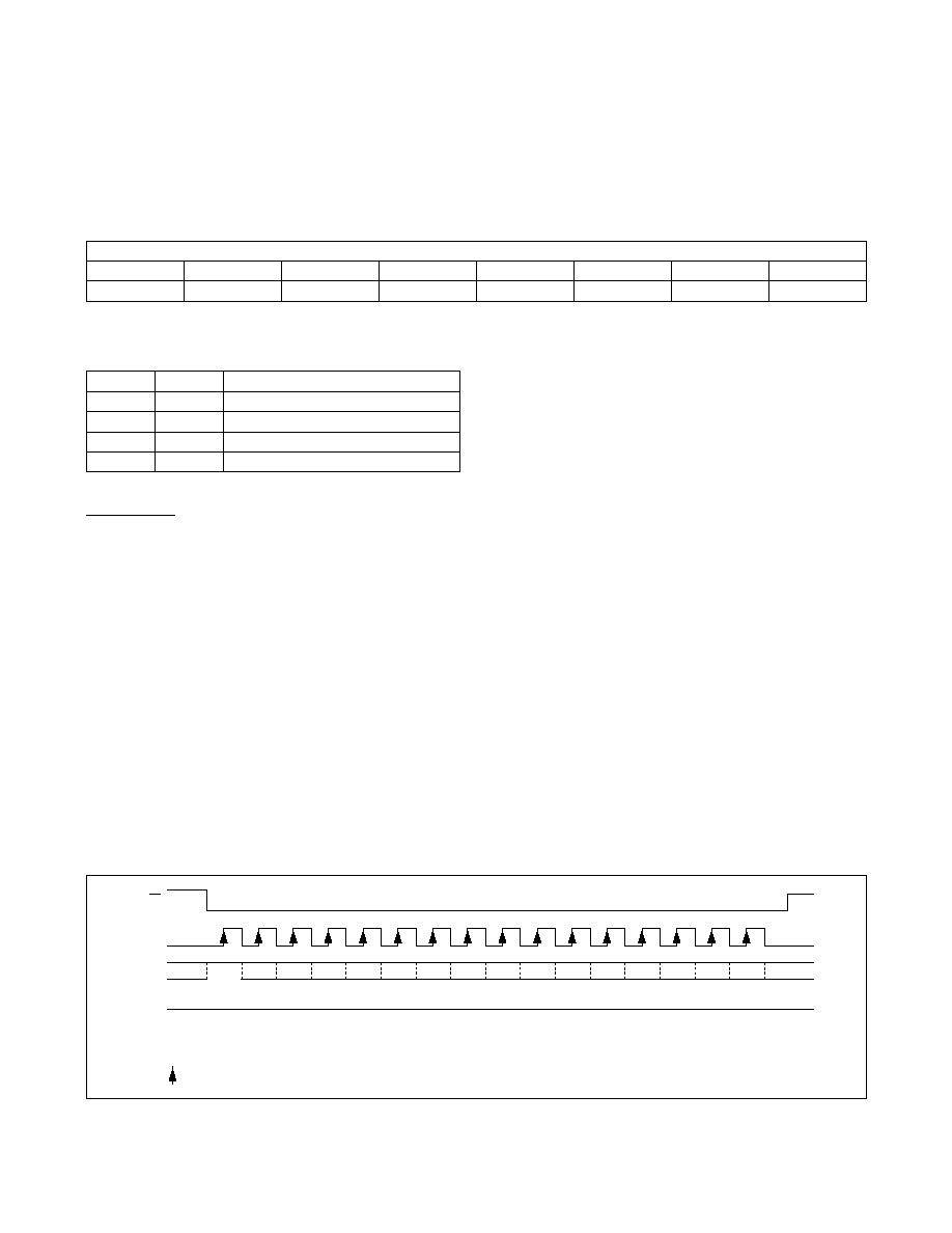
MISO Operation
Before a specific UART has been addressed, all four
UARTs can attempt to drive MISO. To avoid this conten-
tion, the MISO line is held in high impedance during a
write cycle (Figure 18).
During a read cycle, MISO is high impedance for the
first 4 clock cycles of the command byte. Once the SPI
address (U1 and U0) has been properly decoded, the
addressed SPI drives the MISO line (Figure 19).
SPI Burst Access
Burst access allows writing and reading in one block,
by only defining the initial register address in the SPI
command byte. Multiple characters can be loaded into
the TxFIFO by using the THR (0x00) as the initial burst
write address. Similarly, multiple characters can be read
out of the RxFIFO by using the RHR (0x00) as the SPI’s
burst read address. If the SPI burst address is differ-
ent to 0x00, the MAX14830 automatically increments
the register address after each SPI data byte. Efficient
programming of multiple consecutive registers is thus
possible. Chip select, CS/A0, must be kept low during
the whole cycle. The SCLK/SCL clock continues clocking
throughout the burst access cycle. The burst cycle ends
when the SPI master pulls CS/A0 high.
For example, writing 128 bytes into a TxFIFO can be
achieved by a burst write access through the following
sequence:
1) Pull CS/A0 low.
2) Send SPI write command.
3) Send 128 bytes.
4) Release CS/A0.
This takes a total of (1 + 128) x 8 clock cycles.
Table 10. SPI Command Byte Configuration
A[4:0] = Register Address
Figure 18. SPI Write Cycle
Table 11. SPI U1, U0 UART Selection
SCLK
MOSI
MISO
X
CS
AX = REGISTER ADDRESS
UX = UART ADDRESS
DX = EIGHT-BIT REGISTER CONTENTS
= INSTANT AT WHICH MAX14830 SAMPLES MOSI DATA
WU1U0A4A3A2A1A0D7D6D5D4D3D2D1D0
HiZ
SPI COMMAND BYTE
BIT 7
BIT 6
BIT 5
BIT 4
BIT 3
BIT 2
BIT 1
BIT 0
W/R
U1
U0
A4
A3
A2
A1
A0
U1
U0
UART SELECTED
0
UART0
0
1
UART1
1
0
UART2
1
UART3
相关PDF资料 |
PDF描述 |
|---|---|
| V24C12H150BL3 | CONVERTER MOD DC/DC 12V 150W |
| MAX3111EEWI+TG36 | IC UART SPI COMPAT 28-SOIC |
| MAX3100ETG+ | IC UART SPI/MICROWIRE 24-TQFN-EP |
| MAX3140EEI+T | IC UART W/RS485 28-QSOP |
| MAX3110EEWI+TG36 | IC UART SPI COMPAT 28-SOIC |
相关代理商/技术参数 |
参数描述 |
|---|---|
| MAX14830EVKIT# | 功能描述:界面开发工具 MAX14830 Eval Kit RoHS:否 制造商:Bourns 产品:Evaluation Boards 类型:RS-485 工具用于评估:ADM3485E 接口类型:RS-485 工作电源电压:3.3 V |
| MAX14830EVKIT+ | 制造商:Maxim Integrated Products 功能描述:QUAD UART EV-KIT WITH IO-LINK AND MULTIPROTOCOL - Boxed Product (Development Kits) |
| MAX1483C/D+ | 功能描述:RS-485接口IC low-power transceivers for RS-485 and RS-422 communication RoHS:否 制造商:Texas Instruments 数据速率:250 Kbps 工作电源电压:3.3 V 电源电流:750 uA 工作温度范围:- 40 C to + 125 C 安装风格:SMD/SMT 封装 / 箱体:SOIC-8 封装:Tube |
| MAX1483CPA | 功能描述:RS-485接口IC RoHS:否 制造商:Texas Instruments 数据速率:250 Kbps 工作电源电压:3.3 V 电源电流:750 uA 工作温度范围:- 40 C to + 125 C 安装风格:SMD/SMT 封装 / 箱体:SOIC-8 封装:Tube |
| MAX1483CPA+ | 功能描述:RS-422/RS-485 接口 IC Slew-Rate-Limited RS-485 Transceivers RoHS:否 制造商:Maxim Integrated 数据速率:1136 Kbps 工作电源电压:3 V to 5.5 V 电源电流:5.9 mA 工作温度范围:- 40 C to + 85 C 安装风格:SMD/SMT 封装 / 箱体:SOIC-28 封装:Tube |
发布紧急采购,3分钟左右您将得到回复。