- 您现在的位置:买卖IC网 > PDF目录20674 > MAX15022ATI+ (Maxim Integrated)IC REG QD BCK/LINEAR SYNC 28TQFN PDF资料下载
参数资料
| 型号: | MAX15022ATI+ |
| 厂商: | Maxim Integrated |
| 文件页数: | 14/28页 |
| 文件大小: | 0K |
| 描述: | IC REG QD BCK/LINEAR SYNC 28TQFN |
| 产品培训模块: | Lead (SnPb) Finish for COTS Obsolescence Mitigation Program |
| 标准包装: | 60 |
| 拓扑: | 降压(降压)同步(2),线性(LDO)(2) |
| 功能: | 任何功能 |
| 输出数: | 4 |
| 频率 - 开关: | 500kHz ~ 4MHz |
| 电压/电流 - 输出 1: | 0.6 V ~ 5.5 V,4A |
| 电压/电流 - 输出 2: | 0.6 V ~ 5.5 V,2A |
| 电压/电流 - 输出 3: | 控制器 |
| 带 LED 驱动器: | 无 |
| 带监控器: | 无 |
| 带序列发生器: | 是 |
| 电源电压: | 2.5 V ~ 5.5 V |
| 工作温度: | -40°C ~ 125°C |
| 安装类型: | 表面贴装 |
| 封装/外壳: | 28-WFQFN 裸露焊盘 |
| 供应商设备封装: | 28-TQFN-EP(5x5) |
| 包装: | 管件 |
第1页第2页第3页第4页第5页第6页第7页第8页第9页第10页第11页第12页第13页当前第14页第15页第16页第17页第18页第19页第20页第21页第22页第23页第24页第25页第26页第27页第28页
�� �
�
�Dual,� 4A/2A,� 4MHz,� Step-Down� DC-DC�
�Regulator� with� Dual� LDO� Controllers�
�Error� Amplifier�
�The� output� of� the� internal� voltage-mode� error� amplifier�
�(COMP_)� is� provided� for� frequency� compensation� (see�
�the� Compensation� Design� Guidelines� section).� FB_� is�
�the� inverting� input� of� the� error� amplifier.� The� error�
�amplifier� has� an� 80dB� open-loop� gain� and� a� 12MHz�
�gain� bandwidth� (GBW)� product.�
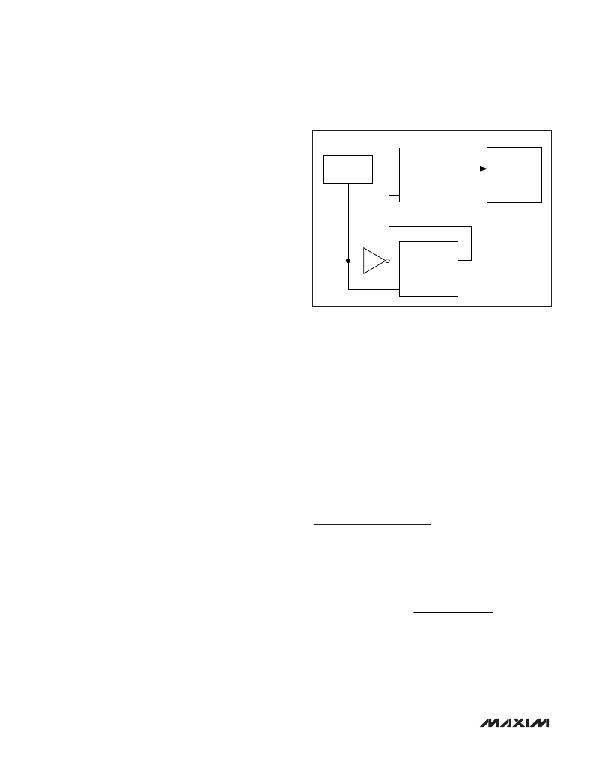
�CURRENT� LIMIT�
�IN�
�COUNT� OF� 4�
�N� CL�
�CLR�
�INITIATE� HICCUP�
�TIMEOUT�
�N� HT�
�Output� Short-Circuit�
�Protection� (Hiccup� Mode)�
�The� MAX15022� features� lossless,� high-side� peak� cur-�
�rent� limit� and� low-side,� valley� current� limit.� At� short� duty�
�cycles,� both� limits� are� active.� At� high� duty� cycles,� only�
�the� high-side� peak� current� limit� is� active.� Either� limit�
�causes� the� hiccup� mode� counter� (N� CL� )� to� increment.�
�For� duty� cycles� less� than� 50%,� the� low-side� valley� cur-�
�IN�
�CLR�
�COUNT� OF� 3�
�N� CLR�
�R� T� [� k� ?� ]� =� SW�
�rent limit is active. Once the high-side MOSFET turns off,�
�the� voltage� across� the� low-side� MOSFET� is� monitored.� If�
�this� voltage� does� not� exceed� the� current-limit� threshold�
�at� the� end� of� the� cycle,� the� high-side� MOSFET� turns� on�
�normally� at� the� start� of� the� next� cycle.� If� the� voltage�
�exceeds� the� current-limit� threshold� just� before� the�
�beginning� of� a� new� PWM� cycle,� the� controller� skips� that�
�cycle.� During� severe� overload� or� short-circuit� condi-�
�tions,� the� switching� frequency� of� the� device� appears� to�
�decrease� because� the� on-time� of� the� low-side� MOSFET�
�extends� beyond� a� clock� cycle.�
�If� the� current-limit� threshold� is� exceeded� for� more� than�
�four� cumulative� clock� cycles� (N� CL� ),� the� device� shuts�
�down� for� 8192� clock� cycles� (hiccup� timeout)� and� then�
�restarts� with� a� soft-start� sequence.� If� three� consecutive�
�cycles� pass� without� a� current-limit� event,� the� count� of�
�N� CL� is� cleared� (see� Figure� 3).� Hiccup� mode� protects�
�the� device� against� a� continuous� output� short� circuit.�
�The� internal� current� limit� is� constant� from� 5.5V� down� to�
�3V� and� decreases� linearly� by� 50%� from� 3V� to� 2V.� See�
�the� Electrical� Characteristics� table.�
�Thermal-Overload� Protection�
�The� MAX15022� features� an� integrated� thermal-overload�
�protection� with� temperature� hysteresis.� Thermal-over-�
�load� protection� limits� the� die� temperature� of� the� device�
�and� protects� it� in� the� event� of� an� extended� thermal� fault�
�condition.� When� the� die� temperature� exceeds� +160°C,�
�an� internal� thermal� sensor� shuts� down� the� device,� turn-�
�ing� off� the� internal� power� MOSFETs� and� allowing� the� die�
�to� cool.� After� the� die� temperature� falls� by� +15°C� (typ),�
�the� device� restarts� with� a� soft-start� sequence.�
�Startup� into� a� Prebiased� Output�
�(Sequencing� Mode)�
�In� sequencing� mode,� the� regulators� start� with� minimal�
�glitch� into� a� prebiased� output� and� soft-stop� is� disabled.�
�Figure� 3.� Hiccup-Mode� Block� Diagram�
�During� soft-start,� both� switches� are� kept� off� until� the�
�PWM� comparator� commands� its� first� PWM� pulse.� Until�
�then,� the� converters� do� not� sink� current� from� the� out-�
�puts.� The� first� PWM� pulse� occurs� when� the� ramping� ref-�
�erence� voltage� increases� above� the� FB_� voltage.�
�LDO� Controllers�
�The� MAX15022� provides� two� additional� LDO� controllers�
�to� drive� external� PNP� pass� transistors.� Connect� the� emit-�
�ter� of� each� PNP� pass� transistor� to� either� the� input� supply�
�or� one� of� the� controller� 1� or� 2� outputs.� Each� LDO� con-�
�troller� features� an� independent� enable� input� and� digital�
�soft-start.� Connect� FB3� and� FB4� to� the� center� tap� of� a�
�resistive� divider� from� the� output� of� the� desired� LDO� con-�
�troller� to� SGND� to� set� the� output� voltage.�
�PWM� Controllers�
�Design� Procedure�
�Setting� the� Switching� Frequency�
�Connect� a� 4.2k� ?� to� 33k� ?� resistor� from� RT� to� SGND� to�
�program� the� switching� frequency� (f� SW� )� from� 500kHz� to�
�4MHz.� Calculate� the� required� resistor� value� R� T� to� set�
�the� switching� frequency� with� the� following� equation:�
�f [kHz]� � 1.067[V]�
�32� [� μ� A� ]� ×� 4[MHz]�
�Higher� frequencies� allow� designs� with� lower� inductor�
�values� and� less� output� capacitance.� At� higher� switch-�
�ing� frequencies� core� losses,� gate-charge� currents,�
�and� switching� losses� increase.� When� operating� from�
�V� AVIN� <� 3V,� the� f� SW� frequency� should� be� derated� to�
�3MHz� (maximum).�
�14�
�______________________________________________________________________________________�
�相关PDF资料 |
PDF描述 |
|---|---|
| T95S685K6R3HSAL | CAP TANT 6.8UF 6.3V 10% 1507 |
| F951A226KAAAQ2 | CAP TANT 22UF 10V 10% 1206 |
| MAX4210DEUA+T | IC CURRENT MONITOR 1.5% 8MSOP |
| 5-1879065-7 | CAP TANT 4.7UF 10V 20% 0805 |
| VI-J61-CX-F3 | CONVERTER MOD DC/DC 12V 75W |
相关代理商/技术参数 |
参数描述 |
|---|---|
| MAX15022ATI+ | 功能描述:直流/直流开关调节器 Dual 4A/2A 4MHz w/Dual LDO Ctlr RoHS:否 制造商:International Rectifier 最大输入电压:21 V 开关频率:1.5 MHz 输出电压:0.5 V to 0.86 V 输出电流:4 A 输出端数量: 最大工作温度: 安装风格:SMD/SMT 封装 / 箱体:PQFN 4 x 5 |
| MAX15022ATI+T | 功能描述:直流/直流开关调节器 Dual 4A/2A 4MHz w/Dual LDO Ctlr RoHS:否 制造商:International Rectifier 最大输入电压:21 V 开关频率:1.5 MHz 输出电压:0.5 V to 0.86 V 输出电流:4 A 输出端数量: 最大工作温度: 安装风格:SMD/SMT 封装 / 箱体:PQFN 4 x 5 |
| MAX15022EVKIT+ | 功能描述:电源管理IC开发工具 MAX15022 Eval Kit RoHS:否 制造商:Maxim Integrated 产品:Evaluation Kits 类型:Battery Management 工具用于评估:MAX17710GB 输入电压: 输出电压:1.8 V |
| MAX15023ETG/V+ | 功能描述:DC/DC 开关控制器 4.5-28V Input Dual Out Synch Buck RoHS:否 制造商:Texas Instruments 输入电压:6 V to 100 V 开关频率: 输出电压:1.215 V to 80 V 输出电流:3.5 A 输出端数量:1 最大工作温度:+ 125 C 安装风格: 封装 / 箱体:CPAK |
| MAX15023ETG/V+T | 功能描述:DC/DC 开关控制器 4.5-28V Input Dual Out Synch Buck RoHS:否 制造商:Texas Instruments 输入电压:6 V to 100 V 开关频率: 输出电压:1.215 V to 80 V 输出电流:3.5 A 输出端数量:1 最大工作温度:+ 125 C 安装风格: 封装 / 箱体:CPAK |
发布紧急采购,3分钟左右您将得到回复。