- 您现在的位置:买卖IC网 > PDF目录1836 > MAX15026CATD+T (Maxim Integrated Products)IC REG CTRLR BUCK PWM VM 14TDFN PDF资料下载
参数资料
| 型号: | MAX15026CATD+T |
| 厂商: | Maxim Integrated Products |
| 文件页数: | 13/23页 |
| 文件大小: | 0K |
| 描述: | IC REG CTRLR BUCK PWM VM 14TDFN |
| 产品培训模块: | Obsolescence Mitigation Program |
| 标准包装: | 2,500 |
| PWM 型: | 电压模式 |
| 输出数: | 1 |
| 频率 - 最大: | 2.4MHz |
| 占空比: | 88% |
| 电源电压: | 4.5 V ~ 28 V |
| 降压: | 是 |
| 升压: | 无 |
| 回扫: | 无 |
| 反相: | 无 |
| 倍增器: | 无 |
| 除法器: | 无 |
| Cuk: | 无 |
| 隔离: | 无 |
| 工作温度: | -40°C ~ 125°C |
| 封装/外壳: | 14-WFDFN 裸露焊盘 |
| 包装: | 带卷 (TR) |
�� �
�
�MAX15026�
�Low-Cost,� Small,� 4.5V� to� 28V� Wide� Operating�
�Range,� DC-DC� Synchronous� Buck� Controller�
�frequency,� input� voltage,� output� voltage,� and� selected�
�OUT�
�LIR� determine� the� inductor� value� as� follows,�
�L� =� OUT� IN� OUT�
�R� 1�
�V� (� V� ?� V�
�V� IN� f� SW� I� OUT� LIR�
�)�
�FB�
�where� V� IN� ,� V� OUT� ,� and� I� OUT� are� typical� values� (so� that�
�efficiency� is� optimum� for� typical� conditions).� The� switch-�
�MAX15026�
�R� 2�
�ing� frequency� is� set� by� R� RT� (see� the� Setting� the�
�Switching� Frequency� section).� The� exact� inductor� value�
�is� not� critical� and� can� be� adjusted� to� make� trade-offs�
�among� size,� cost,� and� efficiency.� Lower� inductor� values�
�minimize� size� and� cost,� but� also� improve� transient�
�response� and� reduce� efficiency� due� to� higher� peak� cur-�
�rents.� On� the� other� hand,� higher� inductance� increases�
�efficiency� by� reducing� the� RMS� current.�
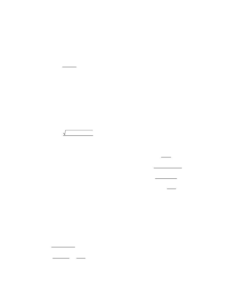
�Figure� 2.� Adjustable� Output� Voltage�
�Setting� the� Switching� Frequency�
�An� external� resistor� connecting� RT� to� GND� sets� the�
�switching� frequency� (f� SW� ).� The� relationship� between�
�f� SW� and� R� RT� is:�
�Find� a� low-loss� inductor� having� the� lowest� possible� DC�
�resistance� that� fits� in� the� allotted� dimensions.� The� satura-�
�tion� current� rating� (I� SAT� )� must� be� high� enough� to� ensure�
�that� saturation� can� occur� only� above� the� maximum� cur-�
�rent-limit� value� (I� CL(MAX)� ),� given� the� tolerance� of� the� on-�
�resistance� of� the� low-side� MOSFET� and� of� the� LIM�
�reference� current� (I� LIM� ).� Combining� these� conditions,�
�f� SW� +� (� 1x10� )x(f� SW� 2� )�
�R� RT� =�
�17.3� � 10� 9�
�?� 7�
�select� an� inductor� with� a� saturation� current� (I� SAT� )� of:�
�I� SAT� ≥� 1.35� x� I� CL(TYP� )�
�where� I� CL(TYP)� is� the� typical� current-limit� set-point.� The�
�where� f� SW� is� in� Hz� and� R� RT� is� in� ?� .� For� example,� a�
�600kHz� switching� frequency� is� set� with� R� RT� =� 27.2k� ?� .�
�Higher� frequencies� allow� designs� with� lower� inductor�
�values� and� less� output� capacitance.� Peak� currents� and�
�I� 2� R� losses� are� lower� at� higher� switching� frequencies,�
�but� core� losses,� gate-charge� currents,� and� switching�
�losses� increase.�
�Inductor� Selection�
�Three� key� inductor� parameters� must� be� specified� for�
�operation� with� the� MAX15026:� inductance� value� (L),�
�inductor� saturation� current� (I� SAT� ),� and� DC� resistance�
�(R� DC� ).� To� determine� the� inductance� value,� select� the�
�ratio� of� inductor� peak-to-peak� AC� current� to� DC� average�
�current� (LIR)� first.� For� LIR� values� which� are� too� high,� the�
�RMS� currents� are� high,� and� therefore� I� 2� R� losses� are�
�factor� 1.35� includes� R� DS(ON)� variation� of� 25%� and� 10%�
�for� the� LIM� reference� current� error.� A� variety� of� inductors�
�from� different� manufacturers� are� available� to� meet� this�
�requirement� (for� example,� Coilcraft� MSS1278-142ML�
�and� other� inductors� from� the� same� series).�
�Setting� the� Valley� Current� Limit�
�The� minimum� current-limit� threshold� must� be� high�
�enough� to� support� the� maximum� expected� load� current�
�with� the� worst-case� low-side� MOSFET� on-resistance�
�value� as� the� R� DS(ON)� of� the� low-side� MOSFET� is� used�
�as� the� current-sense� element.� The� inductor’s� valley� cur-�
�rent� occurs� at� I� LOAD(MAX)� minus� one� half� of� the� ripple�
�current.� The� minimum� value� of� the� current-limit� thresh-�
�old� voltage� (V� ITH� )� must� be� higher� than� the� voltage� on�
�the� low-side� MOSFET� during� the� ripple-current� valley:�
�V� ITH� DS� (� ON� ,� MAX� )� � I� LOAD� (� MAX� )� � ?� 1� ?�
�>� R�
�2� ?�
�high.� Use� high-valued� inductors� to� achieve� low� LIR� val-�
�ues.� Typically,� inductance� is� proportional� to� resistance�
�for� a� given� package� type,� which� again� makes� I� 2� R� losses�
�high� for� very� low� LIR� values.� A� good� compromise�
�?�
�?�
�LIR� ?�
�?�
�between� size� and� loss� is� a� 30%� peak-to-peak� ripple� cur-�
�rent� to� average-current� ratio� (LIR� =� 0.3).� The� switching�
�Maxim� Integrated�
�where� R� DS(ON)� is� the� on-resistance� of� the� low-side�
�MOSFET� in� ohms.� Use� the� maximum� value� for� R� DS(ON)�
�from� the� data� sheet� of� the� low-side� MOSFET.�
�13�
�相关PDF资料 |
PDF描述 |
|---|---|
| MAX15027ATB+T | IC REG LDO ADJ 1A 10-TDFN |
| MAX15030ATB+T | IC REG LDO ADJ .5A 10-TDFN |
| MAX15031ATE+ | IC BOOST CONV/CURRENT MON 16TQFN |
| MAX15032ATA+T | IC REG BOOST ADJ 1A 8TDFN-EP |
| MAX15034AAUI+ | IC REG CTRLR BUCK PWM CM 28TSSOP |
相关代理商/技术参数 |
参数描述 |
|---|---|
| MAX15026CETD+ | 功能描述:DC/DC 开关控制器 4.5-28V Synchronous Buck Controller RoHS:否 制造商:Texas Instruments 输入电压:6 V to 100 V 开关频率: 输出电压:1.215 V to 80 V 输出电流:3.5 A 输出端数量:1 最大工作温度:+ 125 C 安装风格: 封装 / 箱体:CPAK |
| MAX15026CETD+G1D | 制造商:Maxim Integrated Products 功能描述:LOW-COST, SMALL, 4.5V TO 28V WIDE OPERATING RANGE, DC-DC SYN - Rail/Tube |
| MAX15026CETD+T | 功能描述:DC/DC 开关控制器 4.5-28V Synchronous Buck Controller RoHS:否 制造商:Texas Instruments 输入电压:6 V to 100 V 开关频率: 输出电压:1.215 V to 80 V 输出电流:3.5 A 输出端数量:1 最大工作温度:+ 125 C 安装风格: 封装 / 箱体:CPAK |
| MAX15026CETD+TG1D | 制造商:Maxim Integrated Products 功能描述:LOW-COST, SMALL, 4.5V TO 28V WIDE OPERATING RANGE, DC-DC SYN - Tape and Reel |
| MAX15026CETD+TW | 制造商:Maxim Integrated Products 功能描述:LOW-COST SMALL 4.5V TO 28V WIDE OPERATING RANGE DC-DC CONT - Tape and Reel |
发布紧急采购,3分钟左右您将得到回复。