- 您现在的位置:买卖IC网 > PDF目录16795 > MAX16070ETL+ (Maxim Integrated Products)IC SYSTEM MANAGER 12CH 40-TQFN PDF资料下载
参数资料
| 型号: | MAX16070ETL+ |
| 厂商: | Maxim Integrated Products |
| 文件页数: | 11/52页 |
| 文件大小: | 0K |
| 描述: | IC SYSTEM MANAGER 12CH 40-TQFN |
| 产品培训模块: | Lead (SnPb) Finish for COTS Obsolescence Mitigation Program |
| 标准包装: | 50 |
| 应用: | 电源监控器 |
| 电源电压: | 2.8 V ~ 14 V |
| 电流 - 电源: | 4.5mA |
| 工作温度: | -40°C ~ 85°C |
| 安装类型: | 表面贴装 |
| 封装/外壳: | 40-WFQFN 裸露焊盘 |
| 供应商设备封装: | 40-TQFN-EP(6x6) |
| 包装: | 管件 |
第1页第2页第3页第4页第5页第6页第7页第8页第9页第10页当前第11页第12页第13页第14页第15页第16页第17页第18页第19页第20页第21页第22页第23页第24页第25页第26页第27页第28页第29页第30页第31页第32页第33页第34页第35页第36页第37页第38页第39页第40页第41页第42页第43页第44页第45页第46页第47页第48页第49页第50页第51页第52页
�� �
�
�12-Channel/8-Channel,� Flash-Configurable� System�
�Managers� with� Nonvolatile� Fault� Registers�
�Detailed� Description�
�The� MAX16070� monitors� up� to� twelve� system� power� sup-�
�plies� and� the� MAX16071� can� monitor� up� to� eight� system�
�power� supplies.� After� boot-up,� if� EN� is� high� and� the� soft-�
�ware� enable� bit� is� set� to� ‘1,’� monitoring� begins� based� on�
�the� configuration� stored� in� flash.� An� internal� multiplexer�
�cycles� through� each� MON_� input.� At� each� multiplexer�
�stop,� the� 10-bit� ADC� converts� the� monitored� analog� volt-�
�age� to� a� digital� result� and� stores� the� result� in� a� register.�
�Each� time� a� conversion� cycle� (50� F� s,� max)� completes,�
�internal� logic� circuitry� compares� the� conversion� results�
�to� the� overvoltage� and� undervoltage� thresholds� stored� in�
�memory.� When� a� result� violates� a� programmed� threshold,�
�the� conversion� can� be� configured� to� generate� a� fault.�
�GPIO_� can� be� programmed� to� assert� on� combinations�
�of� faults.� Additionally,� faults� can� be� configured� to� shut� off�
�the� system� and� trigger� the� nonvolatile� fault� logger,� which�
�writes� all� fault� information� automatically� to� the� flash� and�
�write-protects� the� data� to� prevent� accidental� erasure.�
�The� MAX16070/MAX16071� contain� both� SMBus� and�
�JTAG� serial� interfaces� for� accessing� registers� and� flash.�
�Use� only� one� interface� at� any� given� time.� For� more� infor-�
�mation� on� how� to� access� the� internal� memory� through�
�these� interfaces,� see� the� SMBus-Compatible� Interface�
�and� JTAG� Serial� Interface� sections.� The� memory� map�
�is� divided� into� three� pages� with� access� controlled� by�
�special� SMBus� and� JTAG� commands.�
�The� factory-default� values� at� POR� (power-on� reset)� for� all�
�RAM� registers� are� ‘0’s.� POR� occurs� when� V� CC� reaches�
�the� undervoltage-lockout� threshold� (UVLO)� of� 2.8V� (max).�
�At� POR,� the� device� begins� a� boot-up� sequence.� During�
�the� boot-up� sequence,� all� monitored� inputs� are� masked�
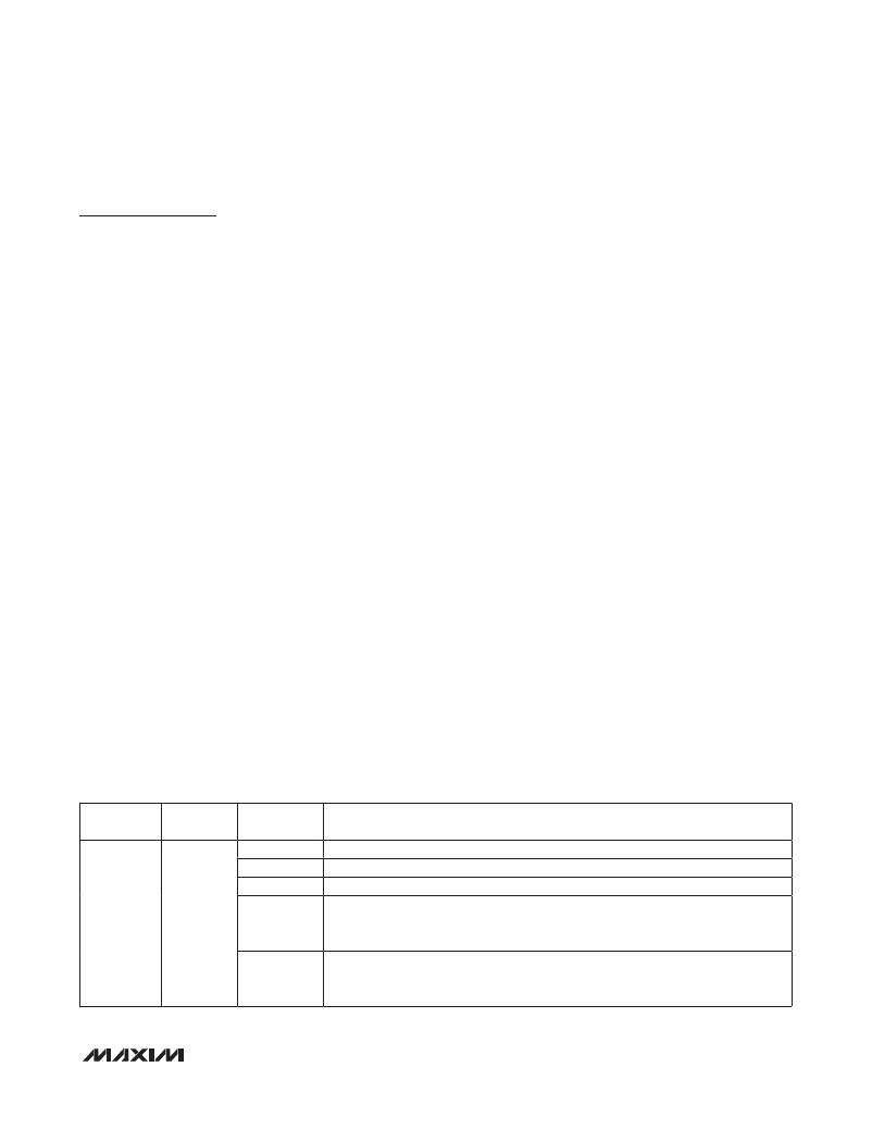
�Table� 1.� Software� Enable� Configurations�
�from� initiating� faults� and� flash� contents� are� copied� to�
�the� respective� register� locations.� During� boot-up,� the�
�MAX16070/MAX16071� are� not� accessible� through� the�
�serial� interface.� The� boot-up� sequence� takes� up� to�
�150� F� s,� after� which� the� device� is� ready� for� normal� opera-�
�tion.� RESET� is� asserted� low� up� to� the� boot-up� phase� and�
�remains� asserted� for� its� programmed� timeout� period� once�
�sequencing� is� completed� and� all� monitored� channels�
�are� within� their� respective� thresholds.� Up� to� the� boot-up�
�phase,� the� GPIO_s� are� high� impedance.�
�Power�
�Apply� 2.8V� to� 14V� to� V� CC� to� power� the� MAX16070/�
�MAX16071.� Bypass� V� CC� to� ground� with� a� 10� F� F� capaci-�
�tor.� Two� internal� voltage� regulators,� ABP� and� DBP,�
�supply� power� to� the� analog� and� digital� circuitry� within�
�the� device.� For� operation� at� 3.6V� or� lower,� disable� the�
�regulators� by� connecting� ABP� and� DBP� to� V� CC� .�
�ABP� is� a� 3.0V� (typ)� voltage� regulator� that� powers� the� inter-�
�nal� analog� circuitry.� Bypass� ABP� to� GND� with� a� 1� F� F� ceram-�
�ic� capacitor� installed� as� close� to� the� device� as� possible.�
�DBP� is� an� internal� 3.0V� (typ)� voltage� regulator.� DBP� pow-�
�ers� flash� and� digital� circuitry.� All� push-pull� outputs� refer� to�
�DBP.� Bypass� the� DBP� output� to� GND� with� a� 1� F� F� ceramic�
�capacitor� installed� as� close� as� possible� to� the� device.�
�Do� not� power� external� circuitry� from� ABP� or� DBP.�
�Enable�
�To� enable� monitoring,� the� voltage� at� EN� must� be� above�
�1.4V� and� the� software� enable� bit� in� r73h[0]� must� be� set�
�to� ‘1.’� To� power� down� and� disable� monitoring,� either� pull�
�EN� below� 1.35V� or� set� the� Software� Enable� bit� to� ‘0.’�
�See� Table� 1� for� the� software� enable� bit� configurations.�
�Connect� EN� to� ABP� if� not� used.�
�REGISTER�
�ADDRESS�
�FLASH�
�ADDRESS�
�BIT� RANGE�
�[0]�
�[1]�
�[2]�
�Software� enable�
�Reserved�
�1� =� Margin� mode� enabled�
�DESCRIPTION�
�Early� warning� threshold� select�
�73h�
�273h�
�[3]�
�0� =� Early� warning� is� undervoltage�
�1� =� Early� warning� is� overvoltage�
�Independent� watchdog� mode� enable�
�[4]�
�1� =� Watchdog� timer� is� independent� of� sequencer�
�0� =� Watchdog� timer� boots� after� sequence� completes�
�______________________________________________________________________________________�
�11�
�相关PDF资料 |
PDF描述 |
|---|---|
| V300C12E150BF3 | CONVERTER MOD DC/DC 12V 150W |
| GBE05DHHT | CONN EDGECARD 10POS 1MM DIP SLD |
| H2MXS-1018M | DIP CABLE - HDM10S/AE10M/X |
| MAX16066ETL+ | IC SYSTEM MANAGER 8CH 40-TQFN |
| H3BBS-1006M | IDC CABLE - HSR10S/AE10M/HSR10S |
相关代理商/技术参数 |
参数描述 |
|---|---|
| MAX16070ETL+ | 功能描述:电流和电力监控器、调节器 12Ch System Monitor w/NV Fault Registers RoHS:否 制造商:STMicroelectronics 产品:Current Regulators 电源电压-最大:48 V 电源电压-最小:5.5 V 工作温度范围:- 40 C to + 150 C 安装风格:SMD/SMT 封装 / 箱体:HPSO-8 封装:Reel |
| MAX16070ETL+T | 功能描述:电流和电力监控器、调节器 12Ch System Monitor w/NV Fault Registers RoHS:否 制造商:STMicroelectronics 产品:Current Regulators 电源电压-最大:48 V 电源电压-最小:5.5 V 工作温度范围:- 40 C to + 150 C 安装风格:SMD/SMT 封装 / 箱体:HPSO-8 封装:Reel |
| MAX16071ETL+ | 功能描述:电流和电力监控器、调节器 8Ch System Monitor w/NV Fault Registers RoHS:否 制造商:STMicroelectronics 产品:Current Regulators 电源电压-最大:48 V 电源电压-最小:5.5 V 工作温度范围:- 40 C to + 150 C 安装风格:SMD/SMT 封装 / 箱体:HPSO-8 封装:Reel |
| MAX16071ETL+T | 功能描述:电流和电力监控器、调节器 8Ch System Monitor w/NV Fault Registers RoHS:否 制造商:STMicroelectronics 产品:Current Regulators 电源电压-最大:48 V 电源电压-最小:5.5 V 工作温度范围:- 40 C to + 150 C 安装风格:SMD/SMT 封装 / 箱体:HPSO-8 封装:Reel |
| MAX16072RS15D0+T | 功能描述:监控电路 uP Supervisor 1.58V Trip RoHS:否 制造商:STMicroelectronics 监测电压数: 监测电压: 欠电压阈值: 过电压阈值: 输出类型:Active Low, Open Drain 人工复位:Resettable 监视器:No Watchdog 电池备用开关:No Backup 上电复位延迟(典型值):10 s 电源电压-最大:5.5 V 最大工作温度:+ 85 C 安装风格:SMD/SMT 封装 / 箱体:UDFN-6 封装:Reel |
发布紧急采购,3分钟左右您将得到回复。