- 您现在的位置:买卖IC网 > PDF目录16795 > MAX16070ETL+ (Maxim Integrated Products)IC SYSTEM MANAGER 12CH 40-TQFN PDF资料下载
参数资料
| 型号: | MAX16070ETL+ |
| 厂商: | Maxim Integrated Products |
| 文件页数: | 41/52页 |
| 文件大小: | 0K |
| 描述: | IC SYSTEM MANAGER 12CH 40-TQFN |
| 产品培训模块: | Lead (SnPb) Finish for COTS Obsolescence Mitigation Program |
| 标准包装: | 50 |
| 应用: | 电源监控器 |
| 电源电压: | 2.8 V ~ 14 V |
| 电流 - 电源: | 4.5mA |
| 工作温度: | -40°C ~ 85°C |
| 安装类型: | 表面贴装 |
| 封装/外壳: | 40-WFQFN 裸露焊盘 |
| 供应商设备封装: | 40-TQFN-EP(6x6) |
| 包装: | 管件 |
第1页第2页第3页第4页第5页第6页第7页第8页第9页第10页第11页第12页第13页第14页第15页第16页第17页第18页第19页第20页第21页第22页第23页第24页第25页第26页第27页第28页第29页第30页第31页第32页第33页第34页第35页第36页第37页第38页第39页第40页当前第41页第42页第43页第44页第45页第46页第47页第48页第49页第50页第51页第52页
�� �
�
 �
�12-Channel/8-Channel,� Flash-Configurable� System�
�Managers� with� Nonvolatile� Fault� Registers�
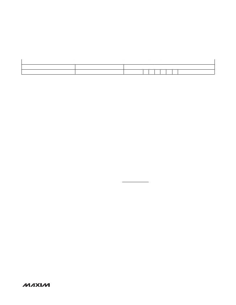
�Table� 25.� 32-Bit� User-Code� Data�
�MSB�
�LSB�
�Don’t� Care�
�00000000000000000�
�SMBus� slave� ID�
�See� Table� 20�
�User� ID� (r8Ah[7:0])�
�USERCODE:� When� the� USERCODE� instruction� latches�
�into� the� parallel� instruction� register,� the� user-code� data�
�register� is� selected.� The� device� user-code� loads� into� the�
�user-code� data� register� on� the� rising� edge� of� TCK� fol-�
�lowing� entry� into� the� capture-DR� state.� Shift-DR� can� be�
�used� to� shift� the� user-code� out� serially� through� TDO.� See�
�Table� 25.� This� instruction� can� be� used� to� help� identify�
�multiple� MAX16070/MAX16071� devices� connected� in� a�
�JTAG� chain.�
�LOAD� ADDRESS:� This� is� an� extension� to� the� standard�
�IEEE� 1149.1� instruction� set� to� support� access� to� the�
�memory� in� the� MAX16070/MAX16071.� When� the� LOAD�
�ADDRESS� instruction� latches� into� the� instruction� register,�
�TDI� connects� to� TDO� through� the� 8-bit� memory� address�
�test� data� register� during� the� shift-DR� state.�
�READ� DATA:� This� is� an� extension� to� the� standard� IEEE�
�1149.1� instruction� set� to� support� access� to� the� memory�
�in� the� MAX16070/MAX16071.� When� the� READ� DATA�
�instruction� latches� into� the� instruction� register,� TDI� con-�
�nects� to� TDO� through� the� 8-bit� memory� read� test� data�
�register� during� the� shift-DR� state.�
�WRITE� DATA:� This� is� an� extension� to� the� standard� IEEE�
�1149.1� instruction� set� to� support� access� to� the� memory�
�in� the� MAX16070/MAX16071.� When� the� WRITE� DATA�
�instruction� latches� into� the� instruction� register,� TDI� con-�
�nects� to� TDO� through� the� 8-bit� memory� write� test� data�
�register� during� the� shift-DR� state.�
�REBOOT:� This� is� an� extension� to� the� standard� IEEE�
�1149.1� instruction� set� to� initiate� a� software-controlled�
�reset� to� the� MAX16070/MAX16071.� When� the� REBOOT�
�instruction� latches� into� the� instruction� register,� the�
�MAX16070/MAX16071� reset� and� immediately� begin� the�
�boot-up� sequence.�
�SAVE:� This� is� an� extension� to� the� standard� IEEE� 1149.1�
�instruction� set� that� triggers� a� fault� log.� The� current� ADC�
�conversion� results� along� with� fault� information� are� saved�
�to� flash� depending� on� the� configuration� of� the� Critical�
�Fault� Log� Control� register� (r6Dh).�
�SETFLSHADD:� This� is� an� extension� to� the� standard� IEEE�
�1149.1� instruction� set� that� allows� access� to� the� flash�
�page.� Flash� registers� include� ADC� conversion� results�
�and� GPIO_� input/output� data.� Use� this� page� to� access�
�registers� 200h� to� 2FFh�
�RSTFLSHADD:� This� is� an� extension� to� the� standard�
�IEEE� 1149.1� instruction� set.� Use� RSTFLSHADD� to� return�
�to� the� default� page� and� disable� access� to� the� flash� page.�
�SETUSRFLSH:� This� is� an� extension� to� the� standard� IEEE�
�1149.1� instruction� set� that� allows� access� to� the� user� flash�
�page.� When� on� the� configuration� flash� page,� send� the�
�SETUSRFLSH� command,� all� addresses� are� recognized�
�as� flash� addresses� only.� Use� this� page� to� access� regis-�
�ters� 300h� to� 3FFh.�
�RSTUSRFLSH:� This� is� an� extension� to� the� standard� IEEE�
�1149.1� instruction� set.� Use� RSTUSRFLSH� to� return� to� the�
�configuration� flash� page� and� disable� access� to� the� user�
�flash.�
�Restrictions� When� Writing� to� Flash�
�Flash� must� be� written� to� 8� bytes� at� a� time.� The� initial�
�address� must� be� aligned� to� 8-byte� boundaries—the� 3�
�LSBs� of� the� initial� address� must� be� ‘000’.� Write� the� 8�
�bytes� using� eight� successive� WRITE� DATA� commands.�
�Applications� Information�
�Device� Behavior� at� Power-Up�
�When� V� CC� is� ramped� from� 0,� the� RESET� output� is� high�
�impedance� until� V� CC� reaches� 1.4V,� at� which� point� RESET�
�goes� low.� All� other� outputs� are� high� impedance� until� V� CC�
�reaches� 2.7V,� when� the� flash� contents� are� copied� into�
�register� memory.� This� takes� 150� F� s� (max),� after� which� the�
�outputs� assume� their� programmed� states.�
�Maintaining� Power�
�During� a� Fault� Condition�
�Power� to� the� MAX16070/MAX16071� must� be� maintained�
�for� a� specific� period� of� time� to� ensure� a� successful� flash�
�fault� log� operation� during� a� fault� that� removes� power� to�
�the� circuit.� Table� 26� shows� the� amount� of� time� required�
�depends� on� the� settings� in� the� fault� control� register�
�(r6Dh[1:0]).�
�Maintain� power� for� shutdown� during� fault� conditions� in�
�applications� where� the� always-on� power� supply� cannot�
�be� relied� upon� by� placing� a� diode� and� a� large� capacitor�
�between� the� voltage� source,� V� IN� ,� and� V� CC� (Figure� 14).�
�______________________________________________________________________________________�
�41�
�相关PDF资料 |
PDF描述 |
|---|---|
| V300C12E150BF3 | CONVERTER MOD DC/DC 12V 150W |
| GBE05DHHT | CONN EDGECARD 10POS 1MM DIP SLD |
| H2MXS-1018M | DIP CABLE - HDM10S/AE10M/X |
| MAX16066ETL+ | IC SYSTEM MANAGER 8CH 40-TQFN |
| H3BBS-1006M | IDC CABLE - HSR10S/AE10M/HSR10S |
相关代理商/技术参数 |
参数描述 |
|---|---|
| MAX16070ETL+ | 功能描述:电流和电力监控器、调节器 12Ch System Monitor w/NV Fault Registers RoHS:否 制造商:STMicroelectronics 产品:Current Regulators 电源电压-最大:48 V 电源电压-最小:5.5 V 工作温度范围:- 40 C to + 150 C 安装风格:SMD/SMT 封装 / 箱体:HPSO-8 封装:Reel |
| MAX16070ETL+T | 功能描述:电流和电力监控器、调节器 12Ch System Monitor w/NV Fault Registers RoHS:否 制造商:STMicroelectronics 产品:Current Regulators 电源电压-最大:48 V 电源电压-最小:5.5 V 工作温度范围:- 40 C to + 150 C 安装风格:SMD/SMT 封装 / 箱体:HPSO-8 封装:Reel |
| MAX16071ETL+ | 功能描述:电流和电力监控器、调节器 8Ch System Monitor w/NV Fault Registers RoHS:否 制造商:STMicroelectronics 产品:Current Regulators 电源电压-最大:48 V 电源电压-最小:5.5 V 工作温度范围:- 40 C to + 150 C 安装风格:SMD/SMT 封装 / 箱体:HPSO-8 封装:Reel |
| MAX16071ETL+T | 功能描述:电流和电力监控器、调节器 8Ch System Monitor w/NV Fault Registers RoHS:否 制造商:STMicroelectronics 产品:Current Regulators 电源电压-最大:48 V 电源电压-最小:5.5 V 工作温度范围:- 40 C to + 150 C 安装风格:SMD/SMT 封装 / 箱体:HPSO-8 封装:Reel |
| MAX16072RS15D0+T | 功能描述:监控电路 uP Supervisor 1.58V Trip RoHS:否 制造商:STMicroelectronics 监测电压数: 监测电压: 欠电压阈值: 过电压阈值: 输出类型:Active Low, Open Drain 人工复位:Resettable 监视器:No Watchdog 电池备用开关:No Backup 上电复位延迟(典型值):10 s 电源电压-最大:5.5 V 最大工作温度:+ 85 C 安装风格:SMD/SMT 封装 / 箱体:UDFN-6 封装:Reel |
发布紧急采购,3分钟左右您将得到回复。