- 您现在的位置:买卖IC网 > PDF目录20781 > MAX16826ATJ+ (Maxim Integrated)IC LED DVR HB PROGR 32TQFN-EP PDF资料下载
参数资料
| 型号: | MAX16826ATJ+ |
| 厂商: | Maxim Integrated |
| 文件页数: | 17/26页 |
| 文件大小: | 0K |
| 描述: | IC LED DVR HB PROGR 32TQFN-EP |
| 产品培训模块: | Lead (SnPb) Finish for COTS Obsolescence Mitigation Program |
| 标准包装: | 60 |
| 恒定电流: | 是 |
| 拓扑: | PWM,SEPIC,升压(升压) |
| 输出数: | 4 |
| 内部驱动器: | 无 |
| 类型 - 主要: | 车载,背光 |
| 类型 - 次要: | 高亮度 LED(HBLED),RGB,白色 LED |
| 频率: | 100kHz ~ 1MHz |
| 电源电压: | 4.75 V ~ 24 V |
| 安装类型: | 表面贴装 |
| 封装/外壳: | 32-WFQFN 裸露焊盘 |
| 供应商设备封装: | 32-TQFN-EP |
| 包装: | 托盘 |
| 工作温度: | -40°C ~ 125°C |
�� �
�
 �
�MAX16826�
�Programmable,� Four-String� HB� LED� Driver� with�
�Output-Voltage� Optimization� and� Fault� Detection�
�Overview� of� the� Digital� Section�
�Figure� 3� shows� the� block� diagram� of� the� digital� section� in�
�the� MAX16826.� The� I� 2� C� serial� interface� provides� flexible�
�control� of� the� IC� and� is� in� charge� of� writing/reading�
�to/from� the� register� file� unit.� The� ADC� block� is� a� 7-bit�
�5-channel� SAR� ADC.� The� eighth� bit� of� the� ADC� data� reg-�
�ister� indicates� an� incomplete� conversion� or� timeout� has�
�occurred.� This� bit� is� set� whenever� the� LED� current� fails� to�
�come� into� regulation� during� the� DIM� PWM� on-time.� This�
�indicates� there� is� either� an� LED� open� condition� or� the�
�CS_� on-time� is� less� than� 2μs.�
�A� reason� for� this� among� other� possibilities� is� an� open�
�LED� string� condition.� This� eighth� or� MSB� bit� can� be�
�tested� to� determine� open� string� faults.�
�I� 2� C� Interface�
�The� MAX16826� internal� I� 2� C� serial� interface� provides�
�flexible� control� of� the� amplitude� of� the� LED� current� in�
�each� string� and� the� switch-mode� regulator� output� volt-�
�?�
�?�
�?�
�?�
�ADC� and� 1� bit� to� indicate� a� timeout� during� the� ADC�
�conversion� cycle.�
�Adjustment� of� the� switching� regulator� output.� This� is�
�used� for� adaptive� voltage� optimization� to� improve�
�overall� efficiency.� The� switching� regulator� output� is�
�downward� adjustable� by� changing� its� reference�
�voltage.� This� uses� a� 7-bit� register.�
�Adjustment� of� the� reference� voltage� of� the� current-�
�sink� regulators.� The� reference� voltage� at� the� nonin-�
�verting� input� of� each� of� the� linear� regulator� drive�
�amplifiers� can� be� changed� to� make� adjustments� in�
�the� current� of� each� LED� string� for� a� given� sense�
�resistor.� The� output� can� be� adjusted� down� from� a�
�maximum� of� 316mV� to� 97mV� in� 1.72mV� increments.�
�Fault� reporting.� When� a� shorted� string� fault� or� an�
�overvoltage� fault� occurs,� the� fault� is� recorded.�
�Standby� mode.� When� a� one� is� entered� into� the�
�standby� register� the� IC� goes� into� standby� mode.�
�age.� It� is� also� able� to� read� the� current� sink� FET� drain�
�voltages,� as� well� as� the� switching� regulator� output� volt-�
�age� through� OVP� and� thus� enable� some� fault� detection�
�and� power� dissipation� minimization.� By� using� an� exter-�
�nal� μC,� the� MAX16826� internal� control� and� status� regis-�
�ters� are� also� accessed� through� the� standard�
�bidirectional,� 2-wire,� I� 2� C� serial� interface.�
�The� I� 2� C� interface� provides� the� following� I/O� functions�
�and� programmability:�
�?� Current� sink� FET� drain� and� switching� regulator� out-�
�put-voltage� measurement.� The� measurement� for�
�each� channel� and� the� regulator� output� is� stored� in�
�its� respective� register� and� can� be� accessed�
�through� the� I� 2� C� interface.� The� SAR� ADC� measures�
�the� drain� voltage� of� each� current� sink� FET� sequen-�
�tially.� This� uses� one� 8-bit� register� for� each� channel�
�to� store� the� measurement� made� by� the� 7-bit� SAR�
�SDA�
�The� 7-bit� I� 2� C� address� is� 58h� and� the� 8-bit� I� 2� C� address�
�is� B1h� for� a� read� operation� and� B0h� for� a� write� opera-�
�tion.� Address� the� MAX16826� using� the� I� 2� C� interface� to�
�read� the� state� of� the� registers� or� to� write� to� the� registers.�
�Upon� a� read� command,� the� MAX16826� transmits� the�
�data� in� the� register� that� the� address� register� is� pointing�
�to.� This� is� done� so� that� the� user� has� the� ability� to� confirm�
�the� data� written� to� a� register� before� the� output� is�
�enabled.� Use� the� fault� register� to� diagnose� any� faults.�
�Serial� Addressing�
�The� I� 2� C� interface� consists� of� a� serial� data� line� (SDA)�
�and� a� serial� clock� line� (SCL)� to� achieve� bidirectional�
�communication� between� the� master� and� the� slave.� The�
�MAX16826� is� a� slave-only� device,� relying� upon� a� mas-�
�ter� to� generate� a� clock� signal.� The� master� initiates� data�
�transfer� to� and� from� the� MAX16826� and� generates� SCL�
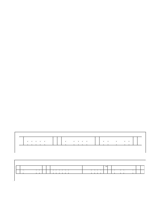
�to� synchronize� the� data� transfer� (Figure� 4).�
�t� LOW�
�t� SU,DAT�
�t� HD,DAT�
�t� SU,STA�
�t� HD,STA�
�t� SU,STO�
�t� BUF�
�SCL�
�t� HD,STA�
�t� HIGH�
�START� CONDITION�
�t� R�
�t� F�
�REPEATED� START� CONDITION�
�STOP�
�CONDITION�
�START�
�CONDITION�
�Figure� 4.� 2-Wire� Serial� Interface� Timing� Detail�
�Maxim� Integrated�
�17�
�相关PDF资料 |
PDF描述 |
|---|---|
| MAX16821CATI+ | IC LED DRIVR HIGH BRIGHT 28-TQFN |
| MAX16821BATI+ | IC LED DRIVR HIGH BRIGHT 28-TQFN |
| LQP03TN3N9C00D | INDUCTOR 3.9NH 170MA 0201 |
| MAX7302AEE+ | IC LED DRIVER LINEAR 16-QSOP |
| GBC10DCAD | CONN EDGECARD 20POS R/A .100 SLD |
相关代理商/技术参数 |
参数描述 |
|---|---|
| MAX16826ATJ/V+ | 制造商:Maxim Integrated Products 功能描述:PROGRAMMABLE, FOUR-STRING HB LED DRIVER WITH OUTPUT-VOLTAGE - Rail/Tube |
| MAX16826ATJ/V+T | 制造商:Maxim Integrated Products 功能描述:PROGRAMMABLE, FOUR-STRING HB LED DRIVER WITH OUTPUT-VOLTAGE - Tape and Reel |
| MAX16826ATJ/VY+ | 制造商:Maxim Integrated Products 功能描述:PROGRAMMABLE, FOUR-STRING HB LED DRIVER WITH OUTPUT-VOLTAGE - Rail/Tube |
| MAX16826ATJ/VY+T | 制造商:Maxim Integrated Products 功能描述:PROGRAMMABLE, FOUR-STRING HB LED DRIVER WITH OUTPUT-VOLTAGE - Tape and Reel |
| MAX16826ATJ+ | 功能描述:LED照明驱动器 Prog 4-String HB RoHS:否 制造商:STMicroelectronics 输入电压:11.5 V to 23 V 工作频率: 最大电源电流:1.7 mA 输出电流: 最大工作温度: 安装风格:SMD/SMT 封装 / 箱体:SO-16N |
发布紧急采购,3分钟左右您将得到回复。