- 您现在的位置:买卖IC网 > PDF目录1841 > MAX1858EEG+T (Maxim Integrated Products)IC REG CTRLR BUCK PWM VM 24-QSOP PDF资料下载
参数资料
| 型号: | MAX1858EEG+T |
| 厂商: | Maxim Integrated Products |
| 文件页数: | 11/21页 |
| 文件大小: | 0K |
| 描述: | IC REG CTRLR BUCK PWM VM 24-QSOP |
| 产品培训模块: | Lead (SnPb) Finish for COTS Obsolescence Mitigation Program |
| 标准包装: | 2,500 |
| PWM 型: | 电压模式 |
| 输出数: | 2 |
| 频率 - 最大: | 660kHz |
| 占空比: | 90% |
| 电源电压: | 4.75 V ~ 23 V |
| 降压: | 是 |
| 升压: | 无 |
| 回扫: | 无 |
| 反相: | 无 |
| 倍增器: | 无 |
| 除法器: | 无 |
| Cuk: | 无 |
| 隔离: | 无 |
| 工作温度: | -40°C ~ 85°C |
| 封装/外壳: | 24-SSOP(0.154",3.90mm 宽) |
| 包装: | 带卷 (TR) |
�� �
�
�Dual� 180°� Out-of-Phase� PWM� Step-Down�
�Controller� with� Power� Sequencing� and� POR�
�V� L�
�INPUT�
�(V� IN� )�
�ply� voltage.� A� 100k� ?� resistor� works� well� for� most� appli-�
�cations.� If� unused,� leave� RST� grounded� or� unconnected.�
�Clock� Synchronization� (SYNC,� CKO)�
�SYNC� serves� two� functions:� SYNC� selects� the� clock� out-�
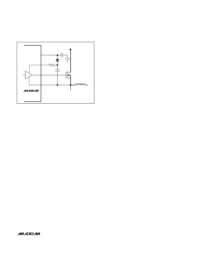
�MAX1858�
�BST_�
�DH_�
�LX_�
�5� ?�
�put� (CKO)� type� used� to� synchronize� slave� controllers,� or�
�it� serves� as� a� clock� input� so� the� MAX1858� can� be� syn-�
�chronized� with� an� external� clock� signal.� This� allows� the�
�MAX1858� to� function� as� either� a� master� or� slave.� CKO�
�provides� a� clock� signal� synchronized� to� the� MAX1858� ’� s�
�switching� frequency,� allowing� either� in-phase� (SYNC� =�
�GND)� or� 90� °� out-of-phase� (SYNC� =� V� L� )� synchronization�
�of� additional� DC-DC� controllers� (Figure� 5).� The�
�MAX1858� supports� the� following� three� operating� modes:�
�?� SYNC� =� GND:� The� CKO� output� frequency� equals�
�REG1� ’� s� switching� frequency� (f� CKO� =� f� DH1� )� and� the�
�CKO� signal� is� in� phase� with� REG1� ’� s� switching� fre-�
�quency.� This� provides� 2-phase� operation� when� syn-�
�Figure� 3.� Reducing� the� Switching-Node� Rise� Time�
�On� the� rising� edge� of� EN� both� controllers� enter� soft-�
�start.� Soft-start� gradually� ramps� up� to� the� reference�
�voltage� seen� by� the� error� amplifier� in� order� to� control�
�the� outputs� ’� rate� of� rise� and� reduce� input� surge� cur-�
�rents� during� startup.� The� soft-start� period� is� 1024� clock�
�cycles� (1024/f� SW� ),� and� the� internal� soft-start� DAC�
�ramps� up� the� voltage� in� 64� steps.� The� output� reaches�
�regulation� when� soft-start� is� completed.� On� the� falling�
�edge� of� EN� both� controllers� simultaneously� enter� soft-�
�stop,� which� reverses� the� soft-start� ramp.� The� part�
�enters� shutdown� after� soft-stop� is� complete.�
�Output-Voltage� Sequencing�
�After� the� startup� circuitry� enables� the� controller,� the�
�MAX1858� begins� the� startup� sequence.� Regulator� 1�
�(OUT1)� powers� up� with� soft-start� enabled.� Once� the� first�
�converter� ’� s� soft-start� sequence� ends,� Regulator� 2� (OUT2)�
�powers� up� with� soft-start� enabled.� Finally,� when� both� con-�
�verters� complete� soft-start� and� both� output� voltages�
�exceed� 90%� of� their� nominal� values,� the� reset� output�
�(� RST� )� goes� high� (see� the� Reset� Output� section).� Soft-stop�
�is� initiated� by� pulling� EN� low.� Soft-stop� occurs� in� reverse�
�order� of� soft-start,� allowing� last-on/first-off� operation.�
�Reset� Output�
�RST� is� an� open-drain� output.� RST� pulls� low� when� either�
�output� falls� below� 90%� of� its� nominal� regulation� voltage.�
�Once� both� outputs� exceed� 90%� of� their� nominal� regula-�
�tion� voltages� and� both� soft-start� cycles� are� completed,�
�RST� goes� high� impedance.� To� obtain� a� logic-voltage� out-�
�put,� connect� a� pullup� resistor� from� RST� to� the� logic� sup-�
�chronized� with� a� second� slave� controller.�
�?� SYNC� =� V� L� :� The� CKO� output� frequency� equals� two�
�times� REG1� ’� s� switching� frequency� (f� CKO� =� 2f� DH1� )�
�and� the� CKO� signal� is� phase� shifted� by� 90� °� with�
�respect� to� REG1� ’� s� switching� frequency.� This� pro-�
�vides� 4-phase� operation� when� synchronized� with� a�
�second� MAX1858� (slave� controller).�
�?� SYNC� Driven� by� External� Oscillator:� The� controller�
�generates� the� clock� signal� by� dividing� down� the�
�SYNC� input� signal,� so� the� switching� frequency� equals�
�half� the� synchronization� frequency� (f� SW� =� f� SYNC� /2).�
�REG1� ’� s� conversion� cycles� initiate� on� the� rising� edge�
�of� the� internal� clock� signal.� The� CKO� output� frequen-�
�cy� and� phase� match� REG1� ’� s� switching� frequency�
�(f� CKO� =� f� DH1� )� and� the� CKO� signal� is� in� phase.� Note�
�that� the� MAX1858� still� requires� R� OSC� when� SYNC� is�
�externally� clocked� and� the� internal� oscillator� frequen-�
�cy� should� be� set� to� 50%� of� the� synchronization� fre-�
�quency� (f� OSC� =� 0.5f� SYNC� ).�
�Thermal� Overload� Protection�
�Thermal� overload� protection� limits� total� power� dissipation�
�in� the� MAX1858.� When� the� device� ’� s� die-junction� tempera-�
�ture� exceeds� T� J� =� +160� °� C,� an� on-chip� thermal� sensor�
�shuts� down� the� device,� forcing� DL_� and� DH_� low,� allow-�
�ing� the� IC� to� cool.� The� thermal� sensor� turns� the� part� on�
�again� after� the� junction� temperature� cools� by� 10� °� C.�
�During� thermal� shutdown,� the� regulators� shut� down,� RST�
�goes� low,� and� soft-start� is� reset.� If� the� V� L� linear-regulator�
�output� is� short-circuited,� thermal-overload� protection� is�
�triggered.�
�______________________________________________________________________________________________________�
�11�
�相关PDF资料 |
PDF描述 |
|---|---|
| MAX1865TEEP+T | IC PWR SUPPLY CONTROLLER 20QSOP |
| MAX1873REEE+T | IC CNTRLR CHARGE LI+ 16-QSOP |
| MAX1874ETE+ | IC LI+ CHARGER DUAL-IN 16-TQFN |
| MAX1875AEEG+ | IC REG CTRLR BUCK PWM VM 24-QSOP |
| MAX1876EEG+T | IC REG CTRLR BUCK PWM VM 24-QSOP |
相关代理商/技术参数 |
参数描述 |
|---|---|
| MAX1858EVKIT | 功能描述:DC/DC 开关控制器 Evaluation Kit for the MAX1858 MAX1875 MAX1876 RoHS:否 制造商:Texas Instruments 输入电压:6 V to 100 V 开关频率: 输出电压:1.215 V to 80 V 输出电流:3.5 A 输出端数量:1 最大工作温度:+ 125 C 安装风格: 封装 / 箱体:CPAK |
| MAX185ACNG | 功能描述:模数转换器 - ADC RoHS:否 制造商:Texas Instruments 通道数量:2 结构:Sigma-Delta 转换速率:125 SPs to 8 KSPs 分辨率:24 bit 输入类型:Differential 信噪比:107 dB 接口类型:SPI 工作电源电压:1.7 V to 3.6 V, 2.7 V to 5.25 V 最大工作温度:+ 85 C 安装风格:SMD/SMT 封装 / 箱体:VQFN-32 |
| MAX185ACNG+ | 功能描述:模数转换器 - ADC RoHS:否 制造商:Texas Instruments 通道数量:2 结构:Sigma-Delta 转换速率:125 SPs to 8 KSPs 分辨率:24 bit 输入类型:Differential 信噪比:107 dB 接口类型:SPI 工作电源电压:1.7 V to 3.6 V, 2.7 V to 5.25 V 最大工作温度:+ 85 C 安装风格:SMD/SMT 封装 / 箱体:VQFN-32 |
| MAX185ACWG | 功能描述:模数转换器 - ADC RoHS:否 制造商:Texas Instruments 通道数量:2 结构:Sigma-Delta 转换速率:125 SPs to 8 KSPs 分辨率:24 bit 输入类型:Differential 信噪比:107 dB 接口类型:SPI 工作电源电压:1.7 V to 3.6 V, 2.7 V to 5.25 V 最大工作温度:+ 85 C 安装风格:SMD/SMT 封装 / 箱体:VQFN-32 |
| MAX185ACWG+ | 功能描述:模数转换器 - ADC RoHS:否 制造商:Texas Instruments 通道数量:2 结构:Sigma-Delta 转换速率:125 SPs to 8 KSPs 分辨率:24 bit 输入类型:Differential 信噪比:107 dB 接口类型:SPI 工作电源电压:1.7 V to 3.6 V, 2.7 V to 5.25 V 最大工作温度:+ 85 C 安装风格:SMD/SMT 封装 / 箱体:VQFN-32 |
发布紧急采购,3分钟左右您将得到回复。