- 您现在的位置:买卖IC网 > PDF目录16798 > MAX1864TEEE+ (Maxim Integrated Products)IC PWR SUPPLY CONTROLLER 16QSOP PDF资料下载
参数资料
| 型号: | MAX1864TEEE+ |
| 厂商: | Maxim Integrated Products |
| 文件页数: | 10/25页 |
| 文件大小: | 0K |
| 描述: | IC PWR SUPPLY CONTROLLER 16QSOP |
| 产品培训模块: | Lead (SnPb) Finish for COTS Obsolescence Mitigation Program |
| 标准包装: | 100 |
| 应用: | 电源控制器 |
| 输入电压: | 4.5 V ~ 28 V |
| 电流 - 电源: | 1mA |
| 工作温度: | -40°C ~ 85°C |
| 安装类型: | 表面贴装 |
| 封装/外壳: | 16-SSOP(0.154",3.90mm 宽) |
| 供应商设备封装: | 16-QSOP |
| 包装: | 管件 |
�� �
�
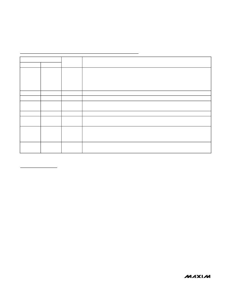
�xDSL/Cable� Modem� Triple/Quintuple� Output�
�Power� Supplies�
�Pin� Description� (continued)�
�MAX1864�
�PIN�
�MAX1865�
�NAME�
�FUNCTION�
�Dual� Mode� Current-Limit� Adjustment� Input.� Connect� to� VL� for� the� default� 250mV�
�current-limit� threshold.� In� adjustable� mode,� the� current-limit� threshold� voltage� is� 1/5th�
�9�
�13�
�ILIM�
�the� voltage� present� at� ILIM.� Connect� to� a� resistive-divider� between� VL� and� GND� to�
�adjust� V� ILIM� between� 1V� and� 2.5V.� The� logic� threshold� for� switchover� to� the� 250mV�
�default� value� is� approximately� VL� -� 1V.�
�10�
�11�
�12�
�13�
�14�
�14�
�15�
�16�
�17�
�18�
�GND�
�DL�
�LX�
�DH�
�BST�
�Ground�
�Low-Side� Gate-Driver� Output.� DL� swings� between� GND� and� VL.�
�Inductor� Connection.� Used� for� current� sense� between� IN� and� LX,� and� used� for� current�
�limit� between� LX� and� GND.�
�High-Side� Gate-Driver� Output.� DH� swings� between� LX� and� BST.�
�Boost� Flying� Capacitor� Connection.� Connect� BST� to� the� external� boost� diode� and�
�capacitor� as� shown� in� the� standard� application� circuit� (Figures� 1� and� 6).�
�Internal� 5V� Linear-Regulator� Output.� Supplies� the� IC� and� powers� the� DL� low-side� gate�
�15�
�19�
�VL�
�driver� and� external� boost� diode� and� capacitor.� Bypass� with� a� 1μF� or� greater� ceramic�
�capacitor� to� GND.�
�16�
�20�
�IN�
�Input� Supply� Voltage,� 4.5V� to� 28V.� Bypass� to� GND� with� a� 1μF� or� greater� ceramic�
�capacitor� close� to� the� IC.�
�Detailed� Description�
�The� MAX1864/MAX1865� power-supply� controllers� pro-�
�vide� system� power� for� cable� and� xDSL� modems.� The�
�main� step-down� DC-DC� controller� operates� in� a� cur-�
�rent-mode� pulse-width-modulation� (PWM)� control�
�scheme� to� ease� compensation� requirements� and� pro-�
�vide� excellent� load-� and� line-transient� response.�
�The� MAX1864� includes� two� analog� gain� blocks� to� regu-�
�late� two� additional� positive� auxiliary� output� voltages,�
�and� the� MAX1865� includes� four� analog� gain� blocks� to�
�regulate� three� additional� positive� and� one� negative� aux-�
�iliary� output� voltages.� The� positive� regulator� gain� blocks�
�can� be� used� to� generate� low-voltage� rails� directly� from�
�the� main� step-down� converter� or� higher� voltages� using�
�coupled� windings� from� the� step-down� converter.� The�
�negative� gain� block� can� be� used� in� conjunction� with� a�
�coupled� winding� to� generate� -5V,� -12V,� or� -15V.�
�DC-DC� Controller�
�The� MAX1864/MAX1865� step-down� converters� use� a�
�pulse-width-modulated� (PWM)� current-mode� control�
�scheme� (Figure� 2).� An� internal� transconductance�
�amplifier� establishes� an� integrated� error� voltage� at� the�
�COMP� pin.� The� heart� of� the� current-mode� PWM� con-�
�troller� is� an� open-loop� comparator� that� compares� the�
�integrated� voltage-feedback� signal� against� the� ampli-�
�fied� current-sense� signal� plus� the� slope� compensation�
�ramp.� At� each� rising� edge� of� the� internal� clock,� the�
�high-side� MOSFET� turns-on� until� the� PWM� comparator�
�trips� or� the� maximum� duty� cycle� is� reached.� During� this�
�on-time,� current� ramps� up� through� the� inductor,� sourc-�
�ing� current� to� the� output� and� storing� energy� in� a� mag-�
�netic� field.� The� current-mode� feedback� system�
�regulates� the� peak� inductor� current� as� a� function� of� the�
�output� voltage� error� signal.� Since� the� average� inductor�
�current� is� nearly� the� same� as� the� peak� inductor� current�
�(assuming� that� the� inductor� value� is� relatively� high� to�
�minimize� ripple� current),� the� circuit� acts� as� a� switch-�
�mode� transconductance� amplifier.� It� pushes� the� output�
�LC� filter� pole,� normally� found� in� a� voltage-mode� PWM,�
�to� a� higher� frequency.� To� preserve� inner� loop� stability�
�and� eliminate� inductor� stair-casing,� a� slope-compensa-�
�tion� ramp� is� summed� into� the� main� PWM� comparator.�
�During� the� second-half� of� the� cycle,� the� high-side� MOS-�
�FET� turns� off� and� the� low-side� N-channel� MOSFET� turns�
�on.� Now� the� inductor� releases� the� stored� energy� as� its�
�current� ramps� down,� providing� current� to� the� output.�
�Therefore,� the� output� capacitor� stores� charge� when� the�
�inductor� current� exceeds� the� load� current� and� dis-�
�charges� when� the� inductor� current� is� lower,� smoothing�
�10�
�______________________________________________________________________________________�
�相关PDF资料 |
PDF描述 |
|---|---|
| RNF-100-1/16-CL-SP | HEAT SHRINK TUBING |
| GBC20DRTH-S734 | CONN EDGECARD 40POS DIP .100 SLD |
| H6MMH-1636M | DIP CABLE - HDM16H/AE16M/HDM16H |
| 0982661101 | CBL 39POS 0.5MM JMPR TYPE A 3" |
| V300B3V3E100BG3 | CONVERTER MOD DC/DC 3.3V 100W |
相关代理商/技术参数 |
参数描述 |
|---|---|
| MAX1864TEEE+ | 功能描述:DC/DC 开关控制器 xDSL/Cable Modem Triple/Quint Output RoHS:否 制造商:Texas Instruments 输入电压:6 V to 100 V 开关频率: 输出电压:1.215 V to 80 V 输出电流:3.5 A 输出端数量:1 最大工作温度:+ 125 C 安装风格: 封装 / 箱体:CPAK |
| MAX1864TEEE+T | 功能描述:电流和电力监控器、调节器 xDSL/Cable Modem Triple/Quint Output RoHS:否 制造商:STMicroelectronics 产品:Current Regulators 电源电压-最大:48 V 电源电压-最小:5.5 V 工作温度范围:- 40 C to + 150 C 安装风格:SMD/SMT 封装 / 箱体:HPSO-8 封装:Reel |
| MAX1864TEEE-T | 功能描述:电流和电力监控器、调节器 RoHS:否 制造商:STMicroelectronics 产品:Current Regulators 电源电压-最大:48 V 电源电压-最小:5.5 V 工作温度范围:- 40 C to + 150 C 安装风格:SMD/SMT 封装 / 箱体:HPSO-8 封装:Reel |
| MAX1864UEEE | 功能描述:电流和电力监控器、调节器 RoHS:否 制造商:STMicroelectronics 产品:Current Regulators 电源电压-最大:48 V 电源电压-最小:5.5 V 工作温度范围:- 40 C to + 150 C 安装风格:SMD/SMT 封装 / 箱体:HPSO-8 封装:Reel |
| MAX1864UEEE-T | 功能描述:电流和电力监控器、调节器 RoHS:否 制造商:STMicroelectronics 产品:Current Regulators 电源电压-最大:48 V 电源电压-最小:5.5 V 工作温度范围:- 40 C to + 150 C 安装风格:SMD/SMT 封装 / 箱体:HPSO-8 封装:Reel |
发布紧急采购,3分钟左右您将得到回复。