- 您现在的位置:买卖IC网 > PDF目录16798 > MAX1864TEEE+ (Maxim Integrated Products)IC PWR SUPPLY CONTROLLER 16QSOP PDF资料下载
参数资料
| 型号: | MAX1864TEEE+ |
| 厂商: | Maxim Integrated Products |
| 文件页数: | 17/25页 |
| 文件大小: | 0K |
| 描述: | IC PWR SUPPLY CONTROLLER 16QSOP |
| 产品培训模块: | Lead (SnPb) Finish for COTS Obsolescence Mitigation Program |
| 标准包装: | 100 |
| 应用: | 电源控制器 |
| 输入电压: | 4.5 V ~ 28 V |
| 电流 - 电源: | 1mA |
| 工作温度: | -40°C ~ 85°C |
| 安装类型: | 表面贴装 |
| 封装/外壳: | 16-SSOP(0.154",3.90mm 宽) |
| 供应商设备封装: | 16-QSOP |
| 包装: | 管件 |
�� �
�
�xDSL/Cable� Modem� Triple/Quintuple� Output�
�Power� Supplies�
�With� low-cost� aluminum� electrolytic� capacitors,� the�
�ESR-induced� ripple� can� be� larger� than� that� caused� by�
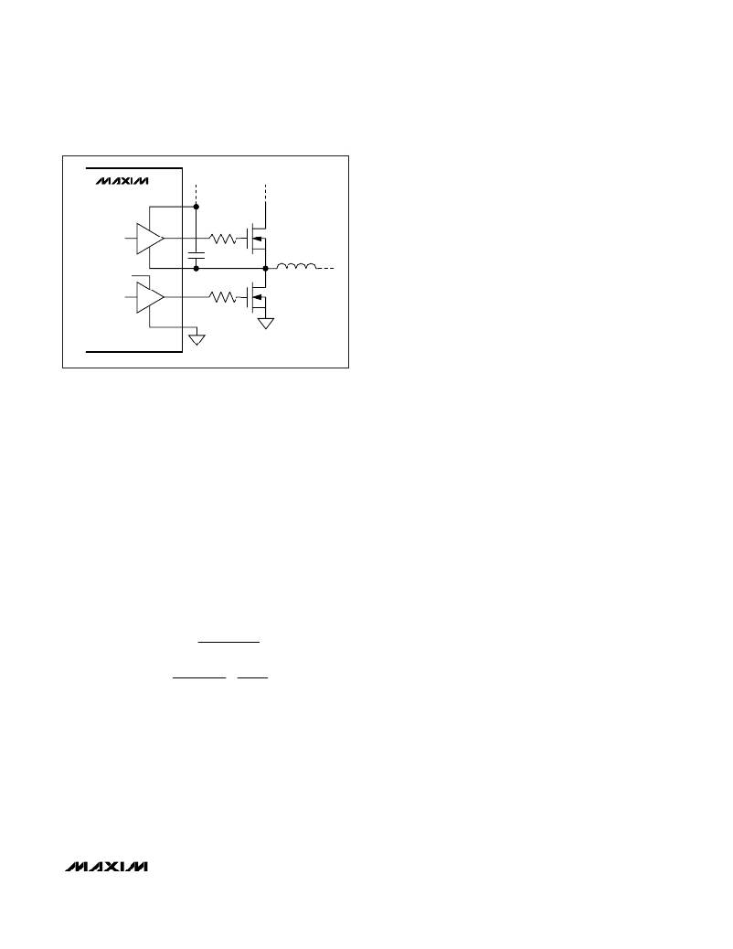
�MAX1864�
�MAX1865�
�TO� VL�
�BST�
�DH�
�LX�
�DH�
�R� GATE�
�(OPTIONAL)�
�C� BST�
�R� GATE�
�(OPTIONAL)�
�N� H�
�N� L�
�L�
�the� current� into� and� out� of� the� capacitor.� Consequently,�
�high-quality� low-ESR� aluminum-electrolytic,� tantalum,�
�polymer,� or� ceramic� filter� capacitors� are� required� to�
�minimize� output� ripple.� Best� results� at� reasonable� cost�
�are� typically� achieved� with� an� aluminum-electrolytic�
�capacitor� in� the� 470μF� range,� in� parallel� with� a� 0.1μF�
�ceramic� capacitor.�
�Since� the� MAX1864/MAX1865� use� a� current-mode� con-�
�trol� scheme,� the� output� capacitor� forms� a� pole� that�
�affects� circuit� stability� (see� Compensation� Design� ).�
�I� P� ?� P�
�I� P� ?� P� =� ?� IN� OUT� ?� ?� OUT� ?�
�GND�
�Figure� 5.� Reducing� the� Switching� EMI�
�Output� Capacitor�
�The� key� selection� parameters� for� the� output� capacitor�
�are� the� actual� capacitance� value,� the� equivalent� series�
�resistance� (ESR),� and� voltage-rating� requirements,�
�which� affect� the� overall� stability,� output� ripple� voltage,�
�and� transient� response.�
�The� output� ripple� has� two� components:� variations� in� the�
�charge� stored� in� the� output� capacitor,� and� the� voltage�
�drop� across� the� capacitor’s� ESR� caused� by� the� current�
�into� and� out� of� the� capacitor:�
�V� RIPPLE� =� V� RIPPLE� (� ESR� )� +� V� RIPPLE� (� C� )�
�The� output� voltage� ripple� as� a� consequence� of� the� ESR�
�and� output� capacitance� is:�
�V� RIPPLE� (� ESR� )� =� I� P� ?� P� ESR�
�V� RIPPLE� (� C� )� =�
�2� C� OUT� ?� SW�
�?� V� -� V� ?� ?� V� ?�
�?� ?� SW� L� ?� ?� V� IN� ?�
�where� I� P-P� is� the� peak-to-peak� inductor� current� (see�
�Inductor� Value� section).� These� equations� are� suitable�
�for� initial� capacitor� selection,� but� final� values� should� be�
�set� by� testing� a� prototype� or� evaluation� circuit.� As� a�
�general� rule,� a� smaller� ripple� current� results� in� less� out-�
�put� ripple.� Since� the� inductor� ripple� current� is� a� factor�
�of� the� inductor� value� and� input� voltage,� the� output� volt-�
�age� ripple� decreases� with� larger� inductance� but�
�increases� with� lower� input� voltages.�
�Furthermore,� the� output� capacitor’s� ESR� also� forms� a�
�zero.�
�The� MAX1864/MAX1865s’� response� to� a� load� transient�
�depends� on� the� selected� output� capacitor.� After� a� load�
�transient,� the� output� instantly� changes� by� ESR� ?�
�Δ� I� LOAD� .� Before� the� controller� can� respond,� the� output�
�will� sag� further,� depending� on� the� inductor� and� output�
�capacitor� values.�
�After� a� short� period� of� time� (see� Typical� Operating�
�Characteristics� ),� the� controller� responds� by� regulating�
�the� output� voltage� back� to� its� nominal� state.� For� appli-�
�cations� that� have� strict� transient� requirements,� low-ESR�
�high-capacitance� electrolytic� capacitors� are� recom-�
�mended� to� minimize� the� transient� voltage� swing.�
�Do� not� exceed� the� capacitor’s� voltage� or� ripple-current�
�ratings.�
�Compensation� Design�
�The� MAX1864/MAX1865� controllers� use� an� internal�
�transconductance� error� amplifier� whose� output� com-�
�pensates� the� control� loop.� Connect� a� series� resistor�
�and� capacitor� between� COMP� and� GND� to� form� a� pole-�
�zero� pair.� The� external� inductor,� high-side� MOSFET,�
�output� capacitor,� compensation� resistor,� and� compen-�
�sation� capacitor� determine� the� loop� stability.� The� induc-�
�tor� and� output� capacitor� are� chosen� based� on�
�performance,� size,� and� cost.� Additionally,� the� compen-�
�sation� resistor� and� capacitor� are� selected� to� optimize�
�control-loop� stability.� The� component� values� shown� in�
�the� standard� application� circuits� (Figures� 1� and� 6)� yield�
�stable� operation� over� a� broad� range� of� input-to-output�
�voltages.�
�The� controller� uses� a� current-mode� control� scheme� that�
�regulates� the� output� voltage� by� forcing� the� required�
�current� through� the� external� inductor,� so� the�
�MAX1864/MAX1865� use� the� voltage� across� the� high-�
�side� MOSFET’s� R� DS(ON)� to� sense� the� inductor� current.�
�Using� the� current-sense� amplifier’s� output� signal� and�
�the� amplified� feedback� voltage,� the� control� loop� deter-�
�mines� the� peak� inductor� current� by:�
�______________________________________________________________________________________�
�17�
�相关PDF资料 |
PDF描述 |
|---|---|
| RNF-100-1/16-CL-SP | HEAT SHRINK TUBING |
| GBC20DRTH-S734 | CONN EDGECARD 40POS DIP .100 SLD |
| H6MMH-1636M | DIP CABLE - HDM16H/AE16M/HDM16H |
| 0982661101 | CBL 39POS 0.5MM JMPR TYPE A 3" |
| V300B3V3E100BG3 | CONVERTER MOD DC/DC 3.3V 100W |
相关代理商/技术参数 |
参数描述 |
|---|---|
| MAX1864TEEE+ | 功能描述:DC/DC 开关控制器 xDSL/Cable Modem Triple/Quint Output RoHS:否 制造商:Texas Instruments 输入电压:6 V to 100 V 开关频率: 输出电压:1.215 V to 80 V 输出电流:3.5 A 输出端数量:1 最大工作温度:+ 125 C 安装风格: 封装 / 箱体:CPAK |
| MAX1864TEEE+T | 功能描述:电流和电力监控器、调节器 xDSL/Cable Modem Triple/Quint Output RoHS:否 制造商:STMicroelectronics 产品:Current Regulators 电源电压-最大:48 V 电源电压-最小:5.5 V 工作温度范围:- 40 C to + 150 C 安装风格:SMD/SMT 封装 / 箱体:HPSO-8 封装:Reel |
| MAX1864TEEE-T | 功能描述:电流和电力监控器、调节器 RoHS:否 制造商:STMicroelectronics 产品:Current Regulators 电源电压-最大:48 V 电源电压-最小:5.5 V 工作温度范围:- 40 C to + 150 C 安装风格:SMD/SMT 封装 / 箱体:HPSO-8 封装:Reel |
| MAX1864UEEE | 功能描述:电流和电力监控器、调节器 RoHS:否 制造商:STMicroelectronics 产品:Current Regulators 电源电压-最大:48 V 电源电压-最小:5.5 V 工作温度范围:- 40 C to + 150 C 安装风格:SMD/SMT 封装 / 箱体:HPSO-8 封装:Reel |
| MAX1864UEEE-T | 功能描述:电流和电力监控器、调节器 RoHS:否 制造商:STMicroelectronics 产品:Current Regulators 电源电压-最大:48 V 电源电压-最小:5.5 V 工作温度范围:- 40 C to + 150 C 安装风格:SMD/SMT 封装 / 箱体:HPSO-8 封装:Reel |
发布紧急采购,3分钟左右您将得到回复。