- 您现在的位置:买卖IC网 > PDF目录2009 > MAX19516ETM+T (Maxim Integrated Products)IC ADC 10BIT 2CH 100MSPS 48TQFN PDF资料下载
参数资料
| 型号: | MAX19516ETM+T |
| 厂商: | Maxim Integrated Products |
| 文件页数: | 21/35页 |
| 文件大小: | 0K |
| 描述: | IC ADC 10BIT 2CH 100MSPS 48TQFN |
| 产品培训模块: | Lead (SnPb) Finish for COTS Obsolescence Mitigation Program |
| 标准包装: | 2,500 |
| 位数: | 10 |
| 采样率(每秒): | 100M |
| 数据接口: | 串行,并联 |
| 转换器数目: | 2 |
| 电压电源: | 模拟和数字 |
| 工作温度: | -40°C ~ 85°C |
| 安装类型: | 表面贴装 |
| 封装/外壳: | 48-WFQFN 裸露焊盘 |
| 供应商设备封装: | 48-TQFN-EP(7x7) |
| 包装: | 带卷 (TR) |
| 输入数目和类型: | 4 个单端,单极;2 个差分,单极 |
第1页第2页第3页第4页第5页第6页第7页第8页第9页第10页第11页第12页第13页第14页第15页第16页第17页第18页第19页第20页当前第21页第22页第23页第24页第25页第26页第27页第28页第29页第30页第31页第32页第33页第34页第35页
MAX19516
Dual-Channel, 10-Bit, 100Msps ADC
28
______________________________________________________________________________________
Digital Outputs
The MAX19516 features a dual CMOS, multiplexable,
reversible data bus. In parallel programming mode,
configure the data outputs (D0_–D9_) for offset binary,
two’s complement, or gray code using the FORMAT
input. Select multiplexed or dual-bus operation using the
OUTSEL input. See the Output Format register (01h) for
details on output formatting using the SPI interface. The
SPI interface offers additional flexibility where D0_–D9_
are reversed, so the LSB appears at D9_ and the MSB
at D0_. OVDD sets the output voltage; set OVDD
between 1.8V and 3.3V. The digital outputs feature pro-
grammable output impedance from 50
to 300. Set
the output impedance for each bus using the CH_ Data
Output Termination Control registers (04h and 05h).
Programmable Data Timing
The MAX19516 provides programmable data timing con-
trol to allow for optimization of timing characteristics to
meet the system timing requirements. The timing adjust-
ment feature also allows for ADC performance improve-
ments by shifting the data output transition away from
the sampling instant. The data timing control signals are
summarized in Table 4. The default settings for timing
adjustment controls are given in Table 5. Many applica-
tions will not require adjustment from the default settings.
The effects of the data timing adjustment settings are
illustrated in Figures 13 and 14. The x axis is sampling
rate and the y axis is data delay in units of clock period.
The solid lines are the nominal data timing characteris-
tics for the 14 available states of DTIME and
DLY_HALF_T. The heavy line represents the nominal
data timing characteristics for the default settings. Note
that the default timing adjustment setting for the
MAX19516 100Msps ADC results in an additional peri-
od of data latency.
Tables 6 and 7 show the recommended timing control
settings versus sampling rate.
The nominal data timing characteristics versus sam-
pling rate for these recommended timing adjustment
settings are shown in Figures 15 and 16.
When DA_BYPASS = 1, the DCLKTIME delay setting
must be equal to or less than the DTIME delay setting,
as shown in Table 8.
Power Management
The SHDN input (pin 7) toggles between any two power-
management states. The Power Management register
(00h) defines each power-management state. In default
state, SHDN = 1 shuts down the MAX19516 and SHDN
= 0 returns to full power. Use of the SHDN input is not
required for power management. For either state of
SHDN, complete power-management flexibility is provid-
ed, including individual ADC channel power-manage-
ment control, through the Power Management register
(00h). The available reduced-power modes are shut-
down and standby. In standby mode, the reference and
duty-cycle equalizer circuits remain active for rapid
wake-up time. In standby mode, the externally applied
clock signal must remain active for the duty-cycle equal-
izer to remain locked. Typical wake-up time from stand-
by mode is 15s. In shutdown mode, all circuits are
turned off except for the reference circuit required for the
integrated self-sensing voltage regulator. If the regulator
is active, there is additional supply current associated
with the regulator circuit when the device is in shutdown.
Typical wake-up time from shutdown mode is 5ms,
which is dominated by the RC time constant on REFIO.
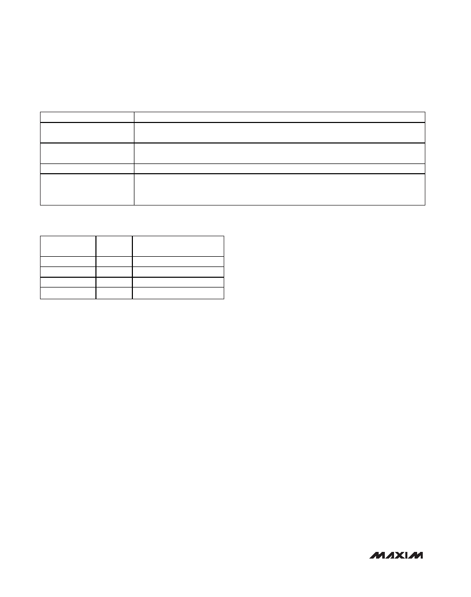
DATA TIMING CONTROL
DESCRIPTION
DA_BYPASS
Data aligner bypass. When this control is active (high), data and DCLK delay is reduced by
approximately 3.4ns (relative to DA_BYPASS = 0).
DLY_HALF_T
When this control is active, data output is delayed by half clock period (T/2). This control does not
delay data output if MUX mode is active.
DTIME<2:0>
Allows adjustment of data output delay in T/16 increments, where T is the sample clock period.
DCLKTIME<2:0>
Provides adjustment of DCLK delay in T/16 increments, where T is the sample clock period. When
DTIME and DCLKTIME are adjusted to the same setting, the rising edge of DCLK occurs T/8 prior
to data transitions.
Table 4. Data Timing Controls
DATA TIMING
CONTROL
DEFAULT
DESCRIPTION
DA_BYPASS
1
Data aligner disabled
DLY_HALF_T
0
No delay
DTIME<2:0>
110
-2T/16 (1.25ns at 100Msps)
DCLKTIME<2:0>
110
-2T/16 (1.25ns at 100Msps)
Table 5. Data Timing Control Default
Settings
相关PDF资料 |
PDF描述 |
|---|---|
| MAX19700ETM+T | IC ANLG FRNT END 48-TQFN |
| MAX19705ETM+ | IC ANLG FRNT END 48-TQFN |
| MAX19706ETM+T | IC ANLG FRNT END 48-TQFN |
| MAX19707ETM+T | IC ANLG FRNT END 48-TQFN |
| MAX19708ETM+ | IC ANLG FRONT END 11MSPS 48-TQFN |
相关代理商/技术参数 |
参数描述 |
|---|---|
| MAX19516EVKIT+ | 功能描述:数据转换 IC 开发工具 MAX19505-07/15-17 Eval Kit RoHS:否 制造商:Texas Instruments 产品:Demonstration Kits 类型:ADC 工具用于评估:ADS130E08 接口类型:SPI 工作电源电压:- 6 V to + 6 V |
| MAX19517ETM+ | 功能描述:模数转换器 - ADC 10-Bit 2Ch 130Msps 1.8V Precision ADC RoHS:否 制造商:Texas Instruments 通道数量:2 结构:Sigma-Delta 转换速率:125 SPs to 8 KSPs 分辨率:24 bit 输入类型:Differential 信噪比:107 dB 接口类型:SPI 工作电源电压:1.7 V to 3.6 V, 2.7 V to 5.25 V 最大工作温度:+ 85 C 安装风格:SMD/SMT 封装 / 箱体:VQFN-32 |
| MAX19517ETM+T | 功能描述:模数转换器 - ADC 10-Bit 2Ch 130Msps 1.8V Precision ADC RoHS:否 制造商:Texas Instruments 通道数量:2 结构:Sigma-Delta 转换速率:125 SPs to 8 KSPs 分辨率:24 bit 输入类型:Differential 信噪比:107 dB 接口类型:SPI 工作电源电压:1.7 V to 3.6 V, 2.7 V to 5.25 V 最大工作温度:+ 85 C 安装风格:SMD/SMT 封装 / 箱体:VQFN-32 |
| MAX19517EVKIT+ | 功能描述:数据转换 IC 开发工具 MAX19517 Eval Kit RoHS:否 制造商:Texas Instruments 产品:Demonstration Kits 类型:ADC 工具用于评估:ADS130E08 接口类型:SPI 工作电源电压:- 6 V to + 6 V |
| MAX1951AESA+ | 功能描述:直流/直流开关调节器 1MHz 2A 2.6-5.5V PWM DC/DC Step-Down RoHS:否 制造商:International Rectifier 最大输入电压:21 V 开关频率:1.5 MHz 输出电压:0.5 V to 0.86 V 输出电流:4 A 输出端数量: 最大工作温度: 安装风格:SMD/SMT 封装 / 箱体:PQFN 4 x 5 |
发布紧急采购,3分钟左右您将得到回复。