- 您现在的位置:买卖IC网 > PDF目录13119 > MAX1997ETJ+ (Maxim Integrated Products)IC PWR SUPPLY TFT LCD 32TQFN PDF资料下载
参数资料
| 型号: | MAX1997ETJ+ |
| 厂商: | Maxim Integrated Products |
| 文件页数: | 20/31页 |
| 文件大小: | 0K |
| 描述: | IC PWR SUPPLY TFT LCD 32TQFN |
| 产品培训模块: | Lead (SnPb) Finish for COTS Obsolescence Mitigation Program |
| 标准包装: | 60 |
| 应用: | 控制器,TFT LCD |
| 输入电压: | 2.7 V ~ 5.5 V |
| 输出数: | 5 |
| 输出电压: | 2.7 V ~ 13 V |
| 工作温度: | 0°C ~ 85°C |
| 安装类型: | 表面贴装 |
| 封装/外壳: | 32-WFQFN 裸露焊盘 |
| 供应商设备封装: | 32-TQFN-EP(5x5) |
| 包装: | 管件 |
第1页第2页第3页第4页第5页第6页第7页第8页第9页第10页第11页第12页第13页第14页第15页第16页第17页第18页第19页当前第20页第21页第22页第23页第24页第25页第26页第27页第28页第29页第30页第31页
�� �
�
�Quintuple/Triple-Output� TFT� LCD� Power� Supplies�
�with� Fault� Protection� and� VCOM� Buffer�
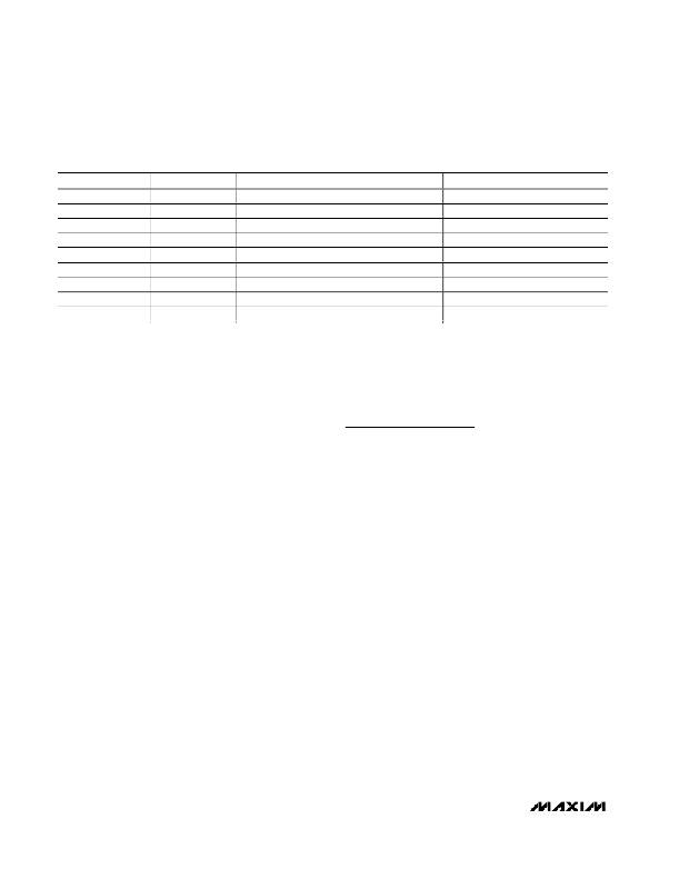
�Table� 3.� Fault� Timer� Duration�
�FREQ� PIN�
�PFLT� PIN*�
�FAULT� TIMER� DURATION� (CLOCK� CYCLES)�
�FAULT� TIMER� DURATION� (ms)�
�GND�
�GND�
�2�
�13�
�21.8�
�Unconnected�
�IN�
�GND�
�GND�
�GND�
�Unconnected�
�2� 14�
�2� 15�
�2� 14�
�21.8�
�21.8�
�43.6�
�Unconnected�
�Unconnected�
�2�
�15�
�43.6�
�IN�
�GND�
�Unconnected�
�IN**�
�2� 16�
�2� 15�
�43.6�
�87.2�
�Unconnected�
�IN**�
�2�
�16�
�87.2�
�IN�
�IN**�
�2� 17�
�87.2�
�*� For� MAX1997� only.�
�**� The� MAX1998� has� PFLT� internally� connected� high.�
�Input� Overcurrent� Protection�
�The� high-side� overcurrent� comparator� of� the�
�MAX1997/MAX1998� provides� input� overcurrent� protec-�
�tion� when� it� is� used� together� with� the� external� P-channel�
�MOSFET� switch� P1� (Figure� 1).� Connect� resistive� volt-�
�age-dividers� from� the� source� and� drain� of� P1� to� GND� to�
�set� the� overcurrent� threshold.� The� center� taps� of� the�
�dividers� are� connected� to� the� overcurrent� comparator�
�inputs� (OCN� and� OCP).� See� Setting� the� Input�
�Overcurrent� Threshold� section� for� information� on� calcu-�
�lating� the� resistor� values.� An� overcurrent� event� acti-�
�vates� the� fault-protection� circuitry.� (See� the� Fault�
�Protection� section.)�
�Fault� Protection�
�During� steady-state� operation,� if� the� output� of� the� main�
�regulator� or� any� of� the� linear-regulator� outputs� is� below�
�its� respective� fault� detection� threshold,� or� an� input� over-�
�current� condition� occurs,� the� MAX1997/MAX1998� acti-�
�vate� an� internal� fault� timer� (Figure� 8).� If� any� condition� or�
�the� combination� of� conditions� indicates� a� continuous�
�fault� for� the� fault� timer� duration� (see� Table� 3),� the�
�MAX1997/MAX1998� set� the� fault� latch,� shutting� down�
�all� the� outputs� except� the� reference� and� the� oscillator.�
�The� fault� detection� circuit� is� disabled� during� the� soft-�
�start� time� of� each� regulator.� Once� the� fault� condition� is�
�removed,� toggle� SHDN� (below� 0.4V)� or� cycle� the� input�
�voltage� (below� 2.2V)� to� clear� the� fault� latch� and� reacti-�
�vate� the� device.�
�Thermal� Shutdown�
�The� thermal� shutdown� feature� limits� total� power� dissipa-�
�tion� in� the� MAX1997/MAX1998.� If� the� junction� tempera-�
�ture� T� J� exceeds� +160� °� C,� a� thermal� sensor� immediately�
�activates� the� fault� protection� (Figure� 2)� and� sets� the�
�fault� latch,� which� shuts� down� all� the� outputs� except� the�
�reference,� allowing� the� device� to� cool� down.� Once� the�
�device� cools� down� by� at� least� 15� °� C,� the� fault� latch� can�
�be� cleared� to� reactivate� the� device.� Toggling� SHDN�
�(below� 0.4V)� or� cycling� the� input� voltage� (below� 2.2V)�
�clears� the� fault� latch.�
�Design� Procedure�
�Main� Step-Up� Regulator�
�Output� Voltage� Selection�
�Set� the� output� voltage� by� connecting� a� resistive� volt-�
�age-divider� from� the� output� (V� MAIN� )� to� GND� with� the�
�center� tap� connected� to� FB� (see� Figure� 1).� Select� R8� to�
�be� 1.5k� ?� or� less� for� optimized� transient� response.� For�
�higher� efficiency,� increase� R8� to� 12k� ?� and� add� lag�
�compensation.� (See� the� Feedback� Compensation� sec-�
�tion.)� Calculate� R7� with� the� following� equation:�
�R7� =� R8� [(V� MAIN� /� V� FB� )� -� 1]�
�where� V� FB� =� 1.242V� -� (D� x� 20mV)� and�
�D� ≈� (V� MAIN� -� V� IN� )� /� V� MAIN� .�
�For� example,� if� V� IN� =� 3V� and� D� ≈� 0.66,� then� V� FB� =�
�1.229V.�
�Choosing� 1.21k� ?� for� R8,� R7� is� 7.65k� ?� .� Use� 7.68k� ?� for�
�R7.� V� MAIN� can� range� from� V� IN� to� 13V.�
�Inductor� Selection�
�The� minimum� inductance� value,� peak� current� rating,�
�series� resistance,� and� size� are� factors� to� consider� when�
�selecting� the� inductor.� These� factors� influence� the� con-�
�verter� ’� s� efficiency,� maximum� output� load� capability,� tran-�
�sient� response� time,� and� output� voltage� ripple.� For� a�
�switching� frequency� of� 1.5MHz,� use� values� between�
�1.8μH� and� 4.7μH.� For� a� switching� frequency� of� 750kHz,�
�use� values� between� 3.3μH� and� 8.2μH.� For� a� switching�
�frequency� of� 375kHz,� use� values� between� 6.8μH� and�
�15μH.�
�20�
�______________________________________________________________________________________�
�相关PDF资料 |
PDF描述 |
|---|---|
| EBM28DTMT-S189 | CONN EDGECARD 56POS R/A .156 SLD |
| ABM15DSES-S243 | CONN EDGECARD 30POS .156 EYELET |
| VI-J6V-CX | CONVERTER MOD DC/DC 5.8V 75W |
| VE-2WB-EW-B1 | CONVERTER MOD DC/DC 95V 100W |
| GBM31DTMT-S189 | CONN EDGECARD 62POS R/A .156 SLD |
相关代理商/技术参数 |
参数描述 |
|---|---|
| MAX1997ETJ+ | 功能描述:其他电源管理 Quint/Triple-Out TFT LCD Power Supply RoHS:否 制造商:Texas Instruments 输出电压范围: 输出电流:4 mA 输入电压范围:3 V to 3.6 V 输入电流: 功率耗散: 工作温度范围:- 40 C to + 110 C 安装风格:SMD/SMT 封装 / 箱体:VQFN-48 封装:Reel |
| MAX1997ETJ+T | 功能描述:LCD 驱动器 Quint/Triple-Out TFT LCD Power Supply RoHS:否 制造商:Maxim Integrated 数位数量:4.5 片段数量:30 最大时钟频率:19 KHz 工作电源电压:3 V to 3.6 V 最大工作温度:+ 85 C 最小工作温度:- 20 C 封装 / 箱体:PDIP-40 封装:Tube |
| MAX1997ETJ-T | 功能描述:其他电源管理 RoHS:否 制造商:Texas Instruments 输出电压范围: 输出电流:4 mA 输入电压范围:3 V to 3.6 V 输入电流: 功率耗散: 工作温度范围:- 40 C to + 110 C 安装风格:SMD/SMT 封装 / 箱体:VQFN-48 封装:Reel |
| MAX1997EVKIT | 制造商:Maxim Integrated Products 功能描述:QUINTUPLE/TRIPLE OUTPUT TFT LCD POWER SUPPLIE - Bulk |
| MAX19983A | 功能描述:上下转换器 RoHS:否 制造商:Texas Instruments 产品:Down Converters 射频:52 MHz to 78 MHz 中频:300 MHz LO频率: 功率增益: P1dB: 工作电源电压:1.8 V, 3.3 V 工作电源电流:120 mA 最大功率耗散:1 W 最大工作温度:+ 85 C 安装风格:SMD/SMT 封装 / 箱体:PQFP-128 |
发布紧急采购,3分钟左右您将得到回复。