- 您现在的位置:买卖IC网 > PDF目录14390 > MAX5099ATJ+ (Maxim Integrated Products)IC REG BUCK SYNC ADJ DL 32TQFN PDF资料下载
参数资料
| 型号: | MAX5099ATJ+ |
| 厂商: | Maxim Integrated Products |
| 文件页数: | 18/27页 |
| 文件大小: | 0K |
| 描述: | IC REG BUCK SYNC ADJ DL 32TQFN |
| 产品培训模块: | Lead (SnPb) Finish for COTS Obsolescence Mitigation Program |
| 标准包装: | 60 |
| 类型: | 降压(降压) |
| 输出类型: | 可调式 |
| 输出数: | 2 |
| 输出电压: | 0.8 V ~ 17.1 V |
| 输入电压: | 4.5 V ~ 19 V |
| PWM 型: | 电压模式 |
| 频率 - 开关: | 200kHz ~ 2.2MHz |
| 电流 - 输出: | 1A,2A |
| 同步整流器: | 是 |
| 工作温度: | -40°C ~ 125°C |
| 安装类型: | 表面贴装 |
| 封装/外壳: | 32-WFQFN 裸露焊盘 |
| 包装: | 管件 |
| 供应商设备封装: | 32-TQFN-EP(5x5) |
第1页第2页第3页第4页第5页第6页第7页第8页第9页第10页第11页第12页第13页第14页第15页第16页第17页当前第18页第19页第20页第21页第22页第23页第24页第25页第26页第27页
�� �
�
�Dual,� 2.2MHz,� Automotive� Synchronous� Buck�
�Converter� with� 80V� Load-Dump� Protection�
�capacitance� requirement.� Note� that� the� two� converters�
�of� the� MAX5099� run� 180°� out-of-phase,� thereby� effec-�
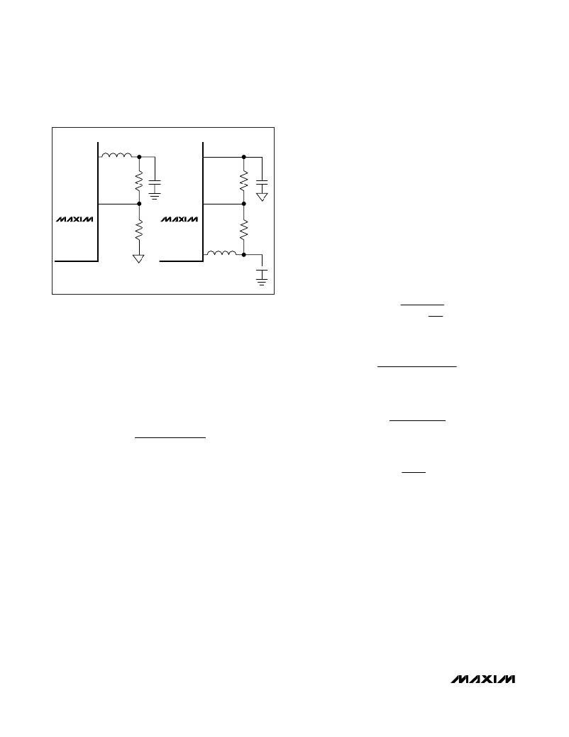
�SOURCE_�
�V� OUT_�
�BYPASS�
�V� OUT_�
�tively� doubling� the� switching� frequency� at� the� input.�
�The� input� ripple� waveform� would� be� unsymmetrical� due�
�FB_�
�R� A�
�FB_�
�R� C�
�to� the� difference� in� load� current� and� duty� cycle� between�
�converter� 1� and� converter� 2.� The� worst-case� mismatch�
�is� when� one� converter� is� at� full� load� while� the� other� is� at�
�no� load� or� in� shutdown.� The� input� ripple� is� comprised� of�
�Δ� V� Q� (caused� by� the� capacitor� discharge)� and� Δ� V� ESR�
�MAX5099�
�R� B�
�MAX5099�
�R� A�
�(caused� by� the� ESR� of� the� capacitor).� Use� ceramic�
�capacitors� with� high� ripple-current� capability� at� the� input�
�connected� between� DRAIN_� and� PGND.� Assume� the�
�SOURCE_�
�contribution� from� the� ESR� and� capacitor� discharge�
�V� OUT_� ≥� 0.8V�
�V� OUT_� <� 0.8V�
�equal� to� 50%.� Calculate� the� input� capacitance� and� ESR�
�required� for� a� specified� ripple� using� the� following� equa-�
�tions:�
�I� OUT� +�
�Figure 2. Adjustable Output Voltage�
�Inductor� Selection�
�Three� key� inductor� parameters� must� be� specified� for�
�operation� with� the� MAX5099:� inductance� value� (L),�
�where�
�ESR� IN� =�
�Δ� V� ESR�
�Δ� I� L�
�2�
�peak� inductor� current� (I� L� ),� and� inductor� saturation� cur-�
�rent� (I� SAT� ).� The� minimum� required� inductance� is� a� func-�
�tion� of� operating� frequency,� input-to-output� voltage�
�differential,� and� the� peak-to-peak� inductor� current� (� Δ� I� L� ).�
�Δ� I� L� =�
�(� V� IN� ?� V� OUT� )� � V� OUT�
�V� IN� � f� SW� � L�
�V� OUT� (� V� IN� ?� V� OUT� )�
�V� IN� ×� f� SW� ×� Δ� I� L�
�A good compromise is to choose ΔI� L� equal to 30% of�
�the� full� load� current.� To� calculate� the� inductance,� use�
�the� following� equation:�
�L� =�
�and�
�where�
�C� IN� =�
�I� OUT� � D� (� 1� ?� D� )�
�Δ� V� Q� ×� f� SW�
�D� =� OUT�
�where V� IN� and V� OUT� are typical values (so that efficien-�
�cy� is� optimum� for� typical� conditions).� The� switching� fre-�
�quency� is� set� by� R� OSC� (see� the� Setting� the� Switching�
�Frequency� section).� The� peak-to-peak� inductor� current,�
�which� reflects� the� peak-to-peak� output� ripple,� is� worse�
�at� the� maximum� input� voltage.� See� the� Output�
�Capacitor� section� to� verify� that� the� worst-case� output�
�ripple� is� acceptable.� The� inductor� saturation� current� is�
�also� important� to� avoid� runaway� current� during� output�
�overload� and� continuous� short� circuit.� Select� the� I� SAT� to�
�be� higher� than� the� maximum� peak� current� limits� of� 4.3A�
�and� 2.6A� for� converter� 1� and� converter� 2.�
�Input� Capacitor�
�The� discontinuous� input� current� waveform� of� the� buck�
�converter� causes� large� ripple� currents� at� the� input.� The�
�switching� frequency,� peak� inductor� current,� and� allow-�
�able� peak-to-peak� voltage� ripple� dictate� the� input�
�V�
�V� IN�
�where� I� OUT� is� the� maximum� output� current� from� either�
�converter� 1� or� converter� 2,� and� D� is� the� duty� cycle� for�
�that� converter.� f� SW� is� the� frequency� of� each� individual�
�converter.� For� example,� at� V� IN� =� 12V,� V� OUT� =� 3.3V� at�
�I� OUT� =� 2A,� and� with� L� =� 3.3� μH,� the� ESR� and� input�
�capacitance� are� calculated� for� a� peak-to-peak� input� rip-�
�ple� of� 100mV� or� less,� yielding� an� ESR� and� capacitance�
�value� of� 20m� Ω� and� 6.8μF� for� 1.25MHz� frequency.� At� low�
�input� voltages,� also� add� one� electrolytic� bulk� capacitor�
�of� at� least� 100μF� on� the� converters’� input� voltage� rail.�
�This� capacitor� acts� as� an� energy� reservoir� to� avoid� pos-�
�sible� undershoot� below� the� undervoltage-lockout� thresh-�
�old� during� power-on� and� transient� loading.�
�18�
�______________________________________________________________________________________�
�相关PDF资料 |
PDF描述 |
|---|---|
| EMM15DTMT-S189 | CONN EDGECARD 30POS R/A .156 SLD |
| LQW15AN40NG00D | INDUCTOR |
| VI-B5V-EX-F3 | CONVERTER MOD DC/DC 5.8V 75W |
| RCM40DCCI | CONN EDGECARD 80POS R/A .156 SLD |
| MAX6467US16D7+T | IC MPU/RESET CIRC 1.575V SOT143 |
相关代理商/技术参数 |
参数描述 |
|---|---|
| MAX5099ATJ+ | 功能描述:直流/直流开关转换器 Dual 2.2MHz Synch Buck Converter RoHS:否 制造商:STMicroelectronics 最大输入电压:4.5 V 开关频率:1.5 MHz 输出电压:4.6 V 输出电流:250 mA 输出端数量:2 最大工作温度:+ 85 C 安装风格:SMD/SMT |
| MAX5099ATJ+T | 功能描述:直流/直流开关转换器 Dual 2.2MHz Synch Buck Converter RoHS:否 制造商:STMicroelectronics 最大输入电压:4.5 V 开关频率:1.5 MHz 输出电压:4.6 V 输出电流:250 mA 输出端数量:2 最大工作温度:+ 85 C 安装风格:SMD/SMT |
| MAX5099EVKIT+ | 功能描述:电源管理IC开发工具 MAX5098A/99 Eval Kit RoHS:否 制造商:Maxim Integrated 产品:Evaluation Kits 类型:Battery Management 工具用于评估:MAX17710GB 输入电压: 输出电压:1.8 V |
| MAX509ACAP | 功能描述:数模转换器- DAC RoHS:否 制造商:Texas Instruments 转换器数量:1 DAC 输出端数量:1 转换速率:2 MSPs 分辨率:16 bit 接口类型:QSPI, SPI, Serial (3-Wire, Microwire) 稳定时间:1 us 最大工作温度:+ 85 C 安装风格:SMD/SMT 封装 / 箱体:SOIC-14 封装:Tube |
| MAX509ACAP+ | 功能描述:数模转换器- DAC 8-Bit 4Ch Precision DAC RoHS:否 制造商:Texas Instruments 转换器数量:1 DAC 输出端数量:1 转换速率:2 MSPs 分辨率:16 bit 接口类型:QSPI, SPI, Serial (3-Wire, Microwire) 稳定时间:1 us 最大工作温度:+ 85 C 安装风格:SMD/SMT 封装 / 箱体:SOIC-14 封装:Tube |
发布紧急采购,3分钟左右您将得到回复。