- 您现在的位置:买卖IC网 > Datasheet目录43 > MAX5930AEEG+ (Maxim Integrated)IC HOT SWAP CTLR PWR SEQ 24QSOP Datasheet资料下载
参数资料
| 型号: | MAX5930AEEG+ |
| 厂商: | Maxim Integrated |
| 文件页数: | 16/23页 |
| 文件大小: | 331K |
| 描述: | IC HOT SWAP CTLR PWR SEQ 24QSOP |
| 产品培训模块: | Lead (SnPb) Finish for COTS Obsolescence Mitigation Program |
| 标准包装: | 50 |
| 类型: | 热交换控制器 |
| 应用: | 通用 |
| 内部开关: | 无 |
| 电源电压: | 1 V ~ 15 V |
| 工作温度: | -40°C ~ 85°C |
| 安装类型: | 表面贴装 |
| 封装/外壳: | 24-SSOP(0.154",3.90mm 宽) |
| 供应商设备封装: | 24-QSOP |
| 包装: | 管件 |
Applications Information
Component Selection
n-Channel MOSFETs
Select the external MOSFETs according to the applica-
tions current levels. Table 6 lists recommended com-
ponents. The MOSFETs on-resistance (R
DS(ON)
)
should be chosen low enough to have a minimum volt-
age drop at full load to limit the MOSFET power dissi-
pation. High R
DS(ON)
causes output ripple if there is a
pulsating load. Determine the device power rating to
accommodate a short-circuit condition on the board at
startup and when the device is in autoretry mode (see
the MOSFET Thermal Considerations section).
Using these devices in latched mode allows the use of
MOSFETs with lower power ratings. A MOSFET typical-
ly withstands single-shot pulses with higher dissipation
than the specified package rating. Table 7 lists some
recommended MOSFET manufacturers.
Sense Resistor
The slow-comparator threshold voltage is adjustable
from 25mV to 100mV. Select a sense resistor that caus-
es a drop equal to the slow-comparator threshold volt-
age at a current level above the maximum normal
operating current. Typically, set the overload current at
1.2 to 1.5 times the full load current. The fast-compara-
tor threshold is two times the slow-comparator thresh-
old in normal operating mode. Choose the sense-
resistor power rating to be greater than or equal to 2 x
(I
OVERLOAD
) x V
SC,TH
. Table 7 lists some recommend-
ed sense-resistor manufacturers.
Slow-Comparator Threshold, R
LIM_
(MAX5930A)
The slow-comparator threshold voltage is adjustable
from 25mV to 100mV, allowing designers to fine-tune
the current-limit threshold for use with standard-value
sense resistors. Low slow-comparator thresholds allow
for increased efficiency by reducing the power dissi-
pated by the sense resistor. Furthermore, the low 25mV
slow-comparator threshold is beneficial when operating
with supply rails down to 1V because it allows a small
percentage of the overall output voltage to be used for
current sensing. The VariableSpeed/BiLevel fault pro-
tection feature offers inherent system immunity against
load transients and noise. This allows the slow-com-
parator threshold to be set close to the maximum nor-
mal operating level without experiencing nuisance
faults. To adjust the slow-comparator threshold, calcu-
late R
LIM_
as follows:
where V
TH
is the desired slow-comparator threshold
voltage. Shorting LIM_ to GND sets V
TH
to 25mV. Do
not leave LIM_ unconnected.
R
V
mV
A
LIM
TH
_
.
=
?/DIV>
25
7 5
Low-Voltage, Triple, Hot-Swap Controllers/
Power Sequencers/Voltage Trackers
16 ______________________________________________________________________________________
LATCH
FAULT MANAGEMENT
Unconnected
Fault condition latches MOSFETs off
Low
Autoretry mode
Table 2. Selecting Fault-Management
Mode (MAX5930A)
POL
STAT_
Low
Asserts low
Unconnected
Asserts high (open-drain)
Table 3. Selecting STAT_ Polarity
(MAX5930A)
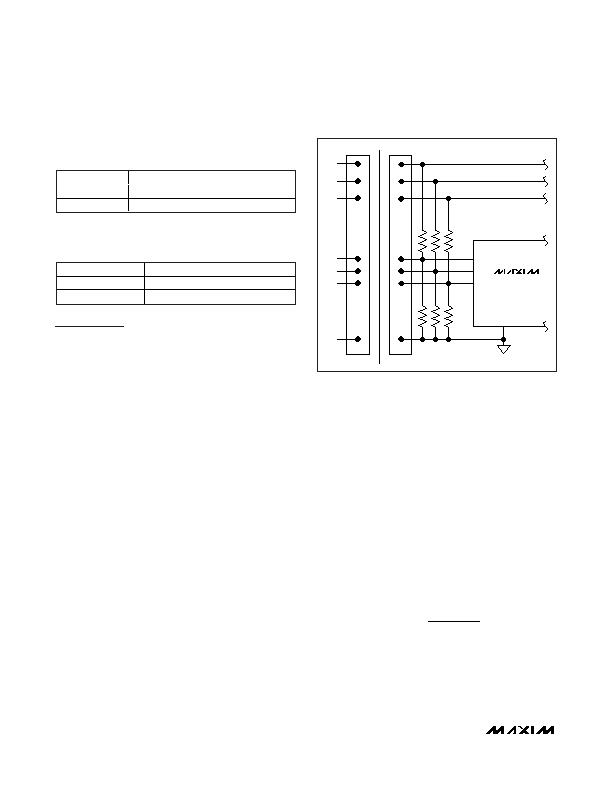
Figure 8. Automatic Turn-On When Input Voltages are Above
their Respective Undervoltage Lockout Threshold (Provided
t
D,UVLO
Requirement is Met)
MAX5930A
MAX5931A
MAX5931B
V
1
ON1
ON2
ON3
GND
GND
ON1
ON2
ON3
REMOVABLE CARD
BACKPLANE
V
2
V
3
相关PDF资料 |
PDF描述 |
|---|---|
| MAX5932ESA+T | IC HOT-SWAP CONTROLLER 8-SOIC |
| MAX5933EESA+ | IC HOT-SWAP CONTROLLER 8-SOIC |
| MAX5934EEE+ | IC HOT-SWAP CONTROLLER 16-QSOP |
| MAX5935EAX+ | IC CTRLR POWER QUAD 36-SSOP |
| MAX5937LCESA+ | IC HOT-SWAP CTRLR -48V 8-SOIC |
相关代理商/技术参数 |
参数描述 |
|---|---|
| MAX5930AEEG+ | 功能描述:热插拔功率分布 Triple Hot-Swap Controller RoHS:否 制造商:Texas Instruments 产品:Controllers & Switches 电流限制: 电源电压-最大:7 V 电源电压-最小:- 0.3 V 工作温度范围: 功率耗散: 安装风格:SMD/SMT 封装 / 箱体:MSOP-8 封装:Tube |
| MAX5930AEEG+T | 功能描述:热插拔功率分布 Triple Hot-Swap Controller RoHS:否 制造商:Texas Instruments 产品:Controllers & Switches 电流限制: 电源电压-最大:7 V 电源电压-最小:- 0.3 V 工作温度范围: 功率耗散: 安装风格:SMD/SMT 封装 / 箱体:MSOP-8 封装:Tube |
| MAX5930EEG | 功能描述:热插拔功率分布 RoHS:否 制造商:Texas Instruments 产品:Controllers & Switches 电流限制: 电源电压-最大:7 V 电源电压-最小:- 0.3 V 工作温度范围: 功率耗散: 安装风格:SMD/SMT 封装 / 箱体:MSOP-8 封装:Tube |
| MAX5930EEG+ | 功能描述:热插拔功率分布 Integrated Circuits (ICs) RoHS:否 制造商:Texas Instruments 产品:Controllers & Switches 电流限制: 电源电压-最大:7 V 电源电压-最小:- 0.3 V 工作温度范围: 功率耗散: 安装风格:SMD/SMT 封装 / 箱体:MSOP-8 封装:Tube |
| MAX5930EEG+T | 功能描述:热插拔功率分布 Integrated Circuits (ICs) RoHS:否 制造商:Texas Instruments 产品:Controllers & Switches 电流限制: 电源电压-最大:7 V 电源电压-最小:- 0.3 V 工作温度范围: 功率耗散: 安装风格:SMD/SMT 封装 / 箱体:MSOP-8 封装:Tube |
发布紧急采购,3分钟左右您将得到回复。