- 您现在的位置:买卖IC网 > PDF目录18780 > MAX7042ATJ+ (Maxim Integrated)IC RCVR RF LP FSK 32-TQFN-EP PDF资料下载
参数资料
| 型号: | MAX7042ATJ+ |
| 厂商: | Maxim Integrated |
| 文件页数: | 10/17页 |
| 文件大小: | 0K |
| 描述: | IC RCVR RF LP FSK 32-TQFN-EP |
| 其它有关文件: | Automotive Product Guide |
| 产品培训模块: | Lead (SnPb) Finish for COTS Obsolescence Mitigation Program |
| 标准包装: | 60 |
| 频率: | 308MHz,315MHz,418MHz,433.92MHz |
| 灵敏度: | -110dBm |
| 数据传输率 - 最大: | 66 kbps |
| 调制或协议: | FSK |
| 应用: | 门禁控制,AMR,ISM,RKE,TPM |
| 电流 - 接收: | 7.2mA |
| 数据接口: | PCB,表面贴装 |
| 天线连接器: | PCB,表面贴装 |
| 电源电压: | 2.4 ~ 3.6 V & 4.5 ~ 5.5 V |
| 工作温度: | -40°C ~ 125°C |
| 封装/外壳: | 32-WFQFN 裸露焊盘 |
| 供应商设备封装: | 32-TQFN-EP(5x5) |
| 包装: | 管件 |
| 产品目录页面: | 1424 (CN2011-ZH PDF) |
�� �
�
�308MHz/315MHz/418MHz/433.92MHz�
�Low-Power,� FSK� Superheterodyne� Receiver�
�Detailed� Description�
�The� MAX7042� CMOS� superheterodyne� receiver� and� a�
�few� external� components� provide� a� complete� FSK�
�receive� chain� from� the� antenna� to� the� digital� output�
�data.� FSK� uses� the� difference� in� frequency� of� the� carri-�
�er� to� represent� a� logic� 0� and� logic� 1.� Depending� on� sig-�
�nal� power� and� component� selection,� data� rates� as� high�
�as� 66kbps� NRZ� can� be� achieved.�
�Frequency� Selection�
�impedance� such� as� printed� circuit� board� (PCB)� trace�
�antenna.� A� nominal� value� of� this� inductor� for� a� 50� ?� input�
�impedance� is� 3.9nH� at� 315MHz� and� 0nH� (short)� at�
�433.92MHz,� but� is� affected� by� the� PCB� trace.� See� the�
�Typical� Operating� Characteristics� for� the� relationship�
�between� the� inductance� and� input� impedance.�
�The� LC� tank� filter� connected� to� LNAOUT� consists� of� L2�
�and� C9� (see� the� Typical� Application� Circuit).� Select� L2�
�and� C9� to� resonate� at� the� desired� RF� input� frequency.�
�The� resonant� frequency� is� given� by:�
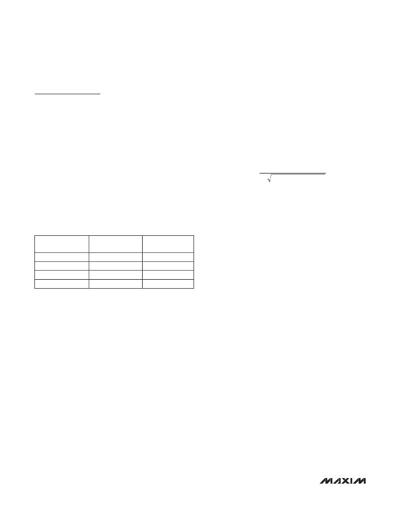
�The� MAX7042� can� be� tuned� to� one� of� four� frequencies�
�using� the� 2� frequency-select� bits� FSEL1� and� FSEL2:�
�308,� 315,� 418,� and� 433.92MHz,� as� shown� in� Table� 1.�
�The� LO� frequencies� are� 32� times� the� crystal� reference�
�f� =�
�1�
�2� π� L� TOTAL� x� C� TOTAL�
�frequencies� of� 9.29063,� 9.50939,� 12.72813,� and�
�13.22563MHz.� The� selected� crystal� frequency� is� used�
�to� calibrate� the� FSK� detector� PLL� so� that� it� operates� at�
�the� middle� of� the� 10.7MHz� IF.�
�Table� 1.� Frequency� Selection� Table�
�where� L� TOTAL� =� L2� +� L� PARASITICS� and� C� TOTAL� =� C9� +�
�C� PARASITICS� .�
�L� PARASITICS� and� C� PARASITICS� include� inductance� and�
�capacitance� of� the� PCB� traces,� package� pins,� mixer�
�input� impedance,� LNA� output� impedance,� etc.� These�
�parasitics� at� high� frequencies� cannot� be� ignored,� and�
�FSEL2�
�0�
�0�
�1�
�1�
�FSEL1�
�0�
�1�
�0�
�1�
�FREQUENCY�
�(MHz)�
�308�
�315�
�418�
�433.92�
�can� have� a� dramatic� effect� on� the� tank� filter� center� fre-�
�quency.� Lab� experimentation� is� required� to� optimize� the�
�center� frequency� of� the� tank.� The� parasitic� capacitance�
�is� generally� 5pF� to� 7pF.�
�There� are� two� ways� to� verify� experimentally� that� the� res-�
�onant� frequency� of� the� tank� is� centered� at� the� desired�
�RF� frequency:�
�Low-Noise� Amplifier� (LNA)�
�The� LNA� is� a� cascode� amplifier� with� off-chip� inductive�
�degeneration.� The� gain� and� the� noise� figure� are� depen-�
�dent� on� both� the� antenna� matching� network� at� the� LNA�
�input� and� the� LC� tank� network� between� the� LNA� output�
�and� the� mixer� input.�
�The� MAX7042� allows� for� user� programmability� of� the�
�LNA� bias� current.� Input� LNASEL� programs� 1x� to� 2x�
�bias� currents� in� increments� of� 0.6mA� from� 0.6mA� to�
�1.2mA.� Setting� LNASEL� to� logic-low� programs� the� LNA�
�to� consume� 1x� bias� current� and� setting� LNASEL� to�
�logic-high� programs� the� LNA� to� consume� 2x� bias� cur-�
�rent.� Larger� bias� currents� yield� better� sensitivity� and�
�gain� at� the� expense� of� current� drain.�
�The� off-chip� inductive� degeneration� is� achieved� by�
�connecting� an� inductor� from� LNASRC� to� AGND.� This�
�inductor� sets� the� real� part� of� the� input� impedance� at�
�LNAIN,� allowing� for� a� more� flexible� match� to� a� low-input�
�1)� Drive� the� crystal� oscillator� externally� and� sweep� both�
�the� RF� frequency� and� the� LO� frequency� (FXTAL� x�
�32)� to� keep� the� IF� at� 10.7MHz� while� monitoring� the�
�RSSI� voltage� (pin� 4).� There� is� a� peak� in� the� RSSI�
�voltage� at� resonance.� The� external� source� must� be�
�AC-coupled� into� XTAL1� and� the� XTAL2� pin� must�
�have� an� AC� bypass� to� ground.� The� recommended�
�drive� power� is� -10dBm.�
�2)� Use� a� network� analyzer� to� measure� the� resonance.�
�The� port� 1� power� from� the� network� analyzer� is� input�
�to� the� receiver,� and� this� power� must� be� -30dBm� or�
�less.� A� coaxial� stub� with� the� center� conductor�
�exposed� (commonly� called� an� RF� “sniffer”� is� used� to�
�monitor� the� tank� power� and� serves� as� the� port� 2�
�input� to� the� network� analyzer.� The� sniffer� should� be�
�placed� in� close� proximity� to,� but� not� actually� touch-�
�ing,� the� tank� inductor.�
�10�
�______________________________________________________________________________________�
�相关PDF资料 |
PDF描述 |
|---|---|
| MAX2112CTI+ | IC TUNER DIR-CONV DVB-S2 28TQFN |
| 0639016101 | CONDUCTOR PUNCH |
| D2VW-5-2MS | MINIATURE BASIC SWITCH |
| 6492 | OSCILLOSCOPE PROBE 350 MHZ X10 |
| FXO-HC736R-60 | OSC 60.00 MHZ 3.3V SMD |
相关代理商/技术参数 |
参数描述 |
|---|---|
| MAX7042ATJ+ | 功能描述:射频接收器 308/315/418/433.9MHz FSK Superhtrdyne Rec RoHS:否 制造商:Skyworks Solutions, Inc. 类型:GPS Receiver 封装 / 箱体:QFN-24 工作频率:4.092 MHz 工作电源电压:3.3 V 封装:Reel |
| MAX7042ATJ+T | 功能描述:射频接收器 308/315/418/433.9MHz FSK Superhtrdyne Rec RoHS:否 制造商:Skyworks Solutions, Inc. 类型:GPS Receiver 封装 / 箱体:QFN-24 工作频率:4.092 MHz 工作电源电压:3.3 V 封装:Reel |
| MAX7042ATJ-T | 制造商:Maxim Integrated Products 功能描述:308MHZ/315MHZ/418MHZ/434MHZ LOW-POWER, FSK SU - Tape and Reel |
| MAX7042EVKIT-315 | 功能描述:射频开发工具 RoHS:否 制造商:Taiyo Yuden 产品:Wireless Modules 类型:Wireless Audio 工具用于评估:WYSAAVDX7 频率: 工作电源电压:3.4 V to 5.5 V |
| MAX7042EVKIT-315+ | 功能描述:射频开发工具 MAX7042 Eval Kit RoHS:否 制造商:Taiyo Yuden 产品:Wireless Modules 类型:Wireless Audio 工具用于评估:WYSAAVDX7 频率: 工作电源电压:3.4 V to 5.5 V |
发布紧急采购,3分钟左右您将得到回复。