- 您现在的位置:买卖IC网 > Datasheet目录341 > MAX8513EVKIT (Maxim Integrated Products)EVAL KIT FOR MAX8513 Datasheet资料下载
参数资料
| 型号: | MAX8513EVKIT |
| 厂商: | Maxim Integrated Products |
| 文件页数: | 25/35页 |
| 文件大小: | 0K |
| 描述: | EVAL KIT FOR MAX8513 |
| 产品培训模块: | Lead (SnPb) Finish for COTS Obsolescence Mitigation Program |
| 标准包装: | 1 |
| 主要目的: | DC/DC,LDO 步降 |
| 输出及类型: | 3,非隔离 |
| 输出电压: | 3.3V,2.5V,12V |
| 电流 - 输出: | 2A,1.5A,100mA |
| 输入电压: | 9 ~ 16 V |
| 稳压器拓扑结构: | 降压 |
| 频率 - 开关: | 1.4MHz |
| 板类型: | 完全填充 |
| 已供物品: | 板 |
| 已用 IC / 零件: | MAX8513 |
第1页第2页第3页第4页第5页第6页第7页第8页第9页第10页第11页第12页第13页第14页第15页第16页第17页第18页第19页第20页第21页第22页第23页第24页当前第25页第26页第27页第28页第29页第30页第31页第32页第33页第34页第35页
�� �
�
�Wide-Input,� High-Frequency,� Triple-Output� Supplies�
�with� Voltage� Monitor� and� Power-On� Reset�
�Use� 6.8k� ?� .�
�C12�
�C� 5� =�
�2�
�π� ×� R� 3� ×� f� PMOD�
�=�
�2�
�π� ×� 6� .� 8� k� ?� ×� 17� .� 4� kHz�
�=� 5� .� 38� nF�
�C11�
�R4�
�Use� 4.7nF.�
�V� OUT1�
�R1�
�EA�
�R3�
�C5�
�R� 1� � R� I�
�R� I� =�
�R� 3� � f� PMOD�
�f� P� 2� � G� EA� (� fZ� 1� -� fZ� 2� )�
�R� 4� =� =�
�R� 1� -� R� I�
�6� .� 8� k� ?� � 17� .� 4� kHz�
�=� =� 583� ?�
�423� kHz� � 0� .� 479�
�13� .� 3� k� ?� � 583� ?�
�=� 609� ?�
�13� .� 3� k� ?� -� 583� ?�
�GAIN�
�(dB)�
�R2�
�V� REF�
�CLOSED-LOOP� GAIN�
�V� COMP�
�Use� 620� ?� .�
�EA� GAIN�
�C� 11� =�
�1�
�2� π� ×� R� 4� ×� f� P� 2�
�=�
�1�
�2� π� ×� 620� ?� ×� 423� kHz�
�=� 607� pF�
�Use� 680pF.�
�Pick� f� P3� =� 700kHz,� which� is� the� midpoint� between� f� ZESR�
�f� Z1�
�f� Z2�
�f� P2�
�f� C�
�f� P3�
�FREQUENCY�
�and� 1/2� the� switching� frequency.�
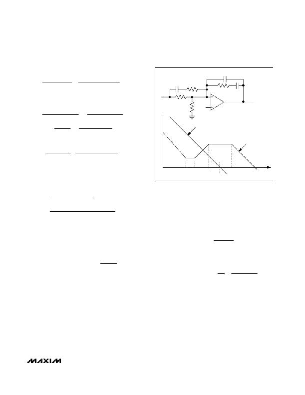
�Figure� 4.� Case� 2:� Error-Amplifier� Compensation� Circuit� (Closed-�
�Loop� and� Error-Amplifier� Gain� Plot)�
�C� 12� =�
�C� 5�
�(� 2� π� ×� C� 5� ×� R� 3� ×� f� P� 3� )� -1�
�The� equations� that� define� the� error� amplifier’s� poles�
�=�
�Use� 33pF.�
�4� .� 7� nF�
�(� 2� π� ×� 4� .� 7� nF� ×� 6� .� 8� k� ?� ×� 700� kHz� )� -1�
�=� 33� .� 7� pF�
�and� zeroes� (f� Z1� ,� f� Z2� ,� f� P2� ,� and� f� P3� )� are� the� same� as� for�
�Case� 1.� However,� f� P2� is� now� lower� than� the� closed-loop�
�crossover� frequency.�
�The� error-amplifier� gain� at� f� C� is:�
�Case� 2:� Electrolytic� Output� Capacitor� (operating� at�
�lower� switching� frequencies,� f� ZESR� <� f� C� )�
�The� modulator� gain� at� f� C� is:�
�G� EA� (� fc� )� =�
�1�
�G� MOD� (� fc� )�
�f�
�G� EA� (� fZ� 1� ?� fZ� 2� )� =� G� EA� (� fc� )� Z� 2� =�
�2�
�G� MOD� (� fc� )� =� G� MOD� (� DC� )� PMOD�
�f� ZESR� f� C�
�The� output� capacitor’s� ESR� zero� frequency� is� higher�
�than� the� LC� double-pole� frequency� but� lower� than� the�
�closed-loop� crossover� frequency.� Here� the� modulator�
�already� has� a� -20dB/decade� slope;� therefore,� the� error-�
�amplifier� gain� must� have� a� 0dB/decade� slope� at� f� C� ,� so�
�the� loop� crosses� over� at� the� desired� -20dB/decade�
�slope.� The� error-amplifier� circuit� configuration� is� the�
�same� as� Case� 1;� however,� the� closed-loop� crossover�
�frequency� is� now� between� f� P2� and� f� P3� ,� as� illustrated� in�
�Figure� 4.�
�And� the� gain� of� the� error� amplifier� between� f� Z1� and�
�f� Z2� is:�
�f� f� Z� 2�
�f� P� 2� f� P� 2� G� MOD� (� fc� )�
�Due� to� the� underdamped� (Q� >� 1)� nature� of� the� output� LC�
�double� pole,� the� error-amplifier� zero� frequencies� must� be�
�set� less� than� the� LC� double-pole� frequency� to� provide�
�adequate� phase� boost.� Set� the� first� zero� of� the� error�
�amplifier,� f� Z1� ,� at� 1/4th� the� LC� double-pole� frequency.� Set�
�the� second� zero,� f� Z2� ,� at� the� LC� double-pole� frequency.�
�Set� the� second� pole,� f� P2� ,� at� f� ZESR� .�
�______________________________________________________________________________________�
�25�
�相关PDF资料 |
PDF描述 |
|---|---|
| MAX8552EUB+ | IC DRIVER MOSFET HS 10-UMAX |
| MAX8595XETA+T | IC LED DRIVR WHITE BCKLGT 8-TDFN |
| MAX8607ETD+T | IC LED DRIVR PHOTO FLASH 14-TDFN |
| MAX8608YETD+T | IC LED DRVR WT/OLED BCKLT 14TDFN |
| MAX8631XETI+T | IC LED DRVR WHITE BCKLGT 28-TQFN |
相关代理商/技术参数 |
参数描述 |
|---|---|
| MAX8514AEI | 功能描述:DC/DC 开关控制器 RoHS:否 制造商:Texas Instruments 输入电压:6 V to 100 V 开关频率: 输出电压:1.215 V to 80 V 输出电流:3.5 A 输出端数量:1 最大工作温度:+ 125 C 安装风格: 封装 / 箱体:CPAK |
| MAX8514AEI-T | 功能描述:DC/DC 开关控制器 RoHS:否 制造商:Texas Instruments 输入电压:6 V to 100 V 开关频率: 输出电压:1.215 V to 80 V 输出电流:3.5 A 输出端数量:1 最大工作温度:+ 125 C 安装风格: 封装 / 箱体:CPAK |
| MAX8514EEI | 功能描述:DC/DC 开关控制器 RoHS:否 制造商:Texas Instruments 输入电压:6 V to 100 V 开关频率: 输出电压:1.215 V to 80 V 输出电流:3.5 A 输出端数量:1 最大工作温度:+ 125 C 安装风格: 封装 / 箱体:CPAK |
| MAX8514EEI-T | 功能描述:DC/DC 开关控制器 RoHS:否 制造商:Texas Instruments 输入电压:6 V to 100 V 开关频率: 输出电压:1.215 V to 80 V 输出电流:3.5 A 输出端数量:1 最大工作温度:+ 125 C 安装风格: 封装 / 箱体:CPAK |
| MAX8515AEXK | 制造商:Maxim Integrated Products 功能描述:WIDE-INPUT 0.6V SHUNT REGULATOR FOR - Rail/Tube 制造商:Rochester Electronics LLC 功能描述: |
发布紧急采购,3分钟左右您将得到回复。