- 您现在的位置:买卖IC网 > PDF目录17278 > MAX8686EVKIT+ (Maxim Integrated Products)BOARD EVAL FOR MAX8686 PDF资料下载
参数资料
| 型号: | MAX8686EVKIT+ |
| 厂商: | Maxim Integrated Products |
| 文件页数: | 13/23页 |
| 文件大小: | 0K |
| 描述: | BOARD EVAL FOR MAX8686 |
| 标准包装: | 1 |
| 主要目的: | DC/DC,步降 |
| 输出及类型: | 1,非隔离 |
| 输出电压: | 0.7 V ~ 5.5 V |
| 电流 - 输出: | 25A |
| 输入电压: | 4.5 V ~ 20 V |
| 稳压器拓扑结构: | 降压 |
| 频率 - 开关: | 300kHz ~ 1MHz |
| 板类型: | 完全填充 |
| 已供物品: | 板 |
| 已用 IC / 零件: | MAX8686 |
�� �
�
�Single/Multiphase,� Step-Down,�
�DC-DC� Converter� Delivers� Up� to� 25A� Per� Phase�
�Current-Limit� Circuit�
�The� current-limit� threshold� is� set� by� a� resistor� between�
�ILIM� and� GND.� Under� soft-overload� conditions,� when�
�the� peak� inductor� current� exceeds� the� selected� current�
�limit,� the� high-side� MOSFET� is� turned� off� immediately�
�and� the� low-side� MOSFET� is� turned� on� and� remains� on�
�to� let� the� inductor� current� ramp� down� until� the� next�
�clock� cycle.� The� converter� does� not� stop� switching� and�
�the� output� voltage� regulation� is� not� guaranteed.� Under�
�severe-overload� or� short-circuit� conditions,� the� foldback�
�and� hiccup� current� limit� is� simultaneously� activated� to�
�reduce� power� dissipation� in� the� inductor,� internal� power�
�MOSFETs,� and� the� upstream� power� source.� Thus,� the�
�circuit� can� withstand� short-circuit� conditions� continu-�
�ously� without� causing� overheating� of� any� component.� If�
�the� device� experiences� a� persistent� overload� condition,�
�the� device� will� autoretry� with� a� soft-start.� The� converter�
�will� resume� normal� operation� after� the� overload� condi-�
�tion� is� removed.�
�The� current-limit� input� is� also� used� to� communicate� faults�
�between� the� devices� in� a� multiphase� configuration.� With�
�any� fault� on� the� slave� or� master� device� (such� as� UVLO� or�
�overtemperature),� the� ILIM� input� is� pulled� low,� which�
�causes� the� other� devices� to� turn� off� both� MOSFETs.�
�Current� Sharing�
�Accurate� current� sharing� is� required� in� a� multiphase� con-�
�verter� to� prevent� some� phases� from� overheating� during�
�soft-start,� steady-state,� and� load� transient.� For� a� convert-�
�er� with� current-mode� control,� the� current� is� proportional�
�to� the� error-amplifier� output� in� the� voltage� feedback� loop.�
�The� error-amplifier� output� (COMP)� of� the� master� is� con-�
�nected� to� the� current� comparator� input� of� all� slave�
�devices.� The� current-sharing� accuracy� is� determined� by�
�the� tolerances� of� the� inductance� and� inductor� DCR,� the�
�input� offset� voltage,� the� gain� of� the� current-sense� ampli-�
�fiers,� and� the� slope� compensation� circuits.�
�The� peak� current-mode� control� is� an� open-loop� current-�
�sharing� scheme,� and� therefore� no� compensation� for�
�The� FREQ� inputs� of� the� master� and� slave� devices� need�
�to� be� connected� together.� FREQ� is� internally� pulled�
�down� to� GFREQ� during� shutdown.�
�Phase� Selection� Input� (PHASE/REFO)�
�For� single-phase� or� master� device� operation,� the�
�PHASE/REFO� can� be� used� as� a� reference� for� the� con-�
�verter� output� voltage� (see� the� Reference� Output�
�(PHASE/REFO)/Reference� Input� (REFIN)� section).� For�
�multiphase� operation,� connect� the� PHASE/REFO� of�
�each� slave� device� to� the� center� tap� of� the� resistor-�
�divider� from� AVL� of� the� master� to� GND.� The� resistor� val-�
�ues� are� selected� to� set� delay� time� between� phases� (see�
�the� Calculating� the� Phase� Voltage� section).� The� PWM�
�clock� cycle� of� slave� devices� starts� 60ns� after� the� rising�
�edge� of� the� voltage� at� FREQ� crosses� the� voltage� at�
�PHASE/REFO.� The� PWM� clock� cycle� of� the� master�
�device� starts� at� the� beginning� of� the� ramp.�
�Remote� Sense� Input� (RS+,� RS-)�
�For� single-phase� or� master� operation,� connect� RS+� to�
�the� sense� point� at� the� load� and� RS-� to� the� GND� sense�
�point� of� the� load.� The� connections� should� be� at� the� out-�
�put� regulation� point� to� eliminate� the� voltage-sense� error�
�caused� by� voltage� drop� between� the� device� and� load.�
�The� RS+� and� RS-� traces� should� be� laid� out� in� parallel� to�
�reduce� noise� coupling.� A� common-mode� filter� to� each�
�sense� trace� should� be� added� if� further� noise� reduction�
�is� needed.�
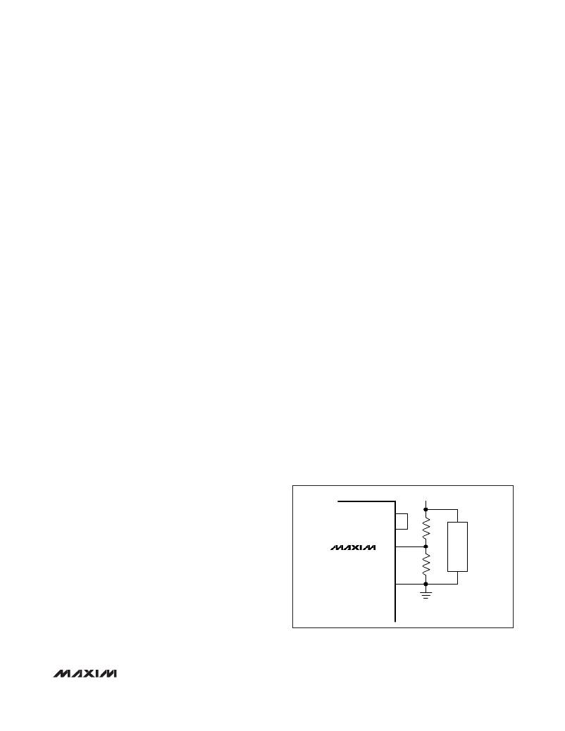
�For� an� output� voltage� higher� than� 3.3V,� tie�
�PHASE/REFO� to� REFIN� and� use� a� resistor-divider� from�
�the� output� regulation� point� to� the� remote� sense� inputs�
�(RS+,� RS-),� as� shown� in� Figure� 1b.�
�For� multiphase� operation,� connect� RS+� and� RS-� to� AVL�
�(slave)� to� select� the� slave� mode.�
�V� OUT�
�PHASE/REFO�
�current� sharing� is� needed� and� no� stability� issue� exists.�
�REFIN�
�R1�
�Switching� Frequency� and�
�Ramp� Generation� (FREQ)�
�The� MAX8686� has� an� adjustable� internal� oscillator� that�
�can� be� set� to� any� frequency� from� 300kHz� to� 1MHz.� To� set�
�MAX8686�
�RS+�
�R2�
�LOAD�
�the� switching� frequency,� connect� a� capacitor� from� the�
�FREQ� to� GFREQ� (see� Setting� the� Switching� Frequency�
�section).�
�A� triangle� ramp� from� 0� to� AVL/2� is� generated� across�
�FREQ� capacitor.� In� a� multiphase� application,� the�
�capacitor� needs� to� be� connected� to� the� master� device.�
�RS-�
�Figure� 1b.� Output� Voltage� Above� 3.3V�
�______________________________________________________________________________________�
�13�
�相关PDF资料 |
PDF描述 |
|---|---|
| EBC07DRTF | CONN EDGECARD 14POS DIP .100 SLD |
| EEV-FC1H3R3R | CAP ALUM 3.3UF 50V 20% SMD |
| EEC12DRAI | CONN EDGECARD 24POS R/A .100 SLD |
| ECC17DCMS | CONN EDGECARD 34POS .100 WW |
| R1D-1524 | CONV DC/DC 1W 15VIN +/-24VOUT |
相关代理商/技术参数 |
参数描述 |
|---|---|
| MAX8686EVKIT# | 功能描述:电源管理IC开发工具 MAX8686 Eval Kit RoHS:否 制造商:Maxim Integrated 产品:Evaluation Kits 类型:Battery Management 工具用于评估:MAX17710GB 输入电压: 输出电压:1.8 V |
| MAX8686EVKIT+ | 功能描述:电源管理IC开发工具 MAX8686 Eval Kit RoHS:否 制造商:Maxim Integrated 产品:Evaluation Kits 类型:Battery Management 工具用于评估:MAX17710GB 输入电压: 输出电压:1.8 V |
| MAX8687ETL+ | 制造商:Maxim Integrated Products 功能描述:SINGLE /MULTIPHASE, DC/DC CONVERTER - Rail/Tube |
| MAX8688AHETG+ | 功能描述:电流和电力监控器、调节器 Digital Power-Supply Controller/Monitor RoHS:否 制造商:STMicroelectronics 产品:Current Regulators 电源电压-最大:48 V 电源电压-最小:5.5 V 工作温度范围:- 40 C to + 150 C 安装风格:SMD/SMT 封装 / 箱体:HPSO-8 封装:Reel |
| MAX8688AHETG+T | 功能描述:电流和电力监控器、调节器 Digital Power-Supply Controller/Monitor RoHS:否 制造商:STMicroelectronics 产品:Current Regulators 电源电压-最大:48 V 电源电压-最小:5.5 V 工作温度范围:- 40 C to + 150 C 安装风格:SMD/SMT 封装 / 箱体:HPSO-8 封装:Reel |
发布紧急采购,3分钟左右您将得到回复。