- 您现在的位置:买卖IC网 > PDF目录69018 > MAXQ7666BATM+ (MAXIM INTEGRATED PRODUCTS INC) RISC MICROCONTROLLER, QCC48 PDF资料下载
参数资料
| 型号: | MAXQ7666BATM+ |
| 厂商: | MAXIM INTEGRATED PRODUCTS INC |
| 元件分类: | 微控制器/微处理器 |
| 英文描述: | RISC MICROCONTROLLER, QCC48 |
| 封装: | 7 X 7 MM, ROHS COMPLAINT, TQFN-48 |
| 文件页数: | 18/49页 |
| 文件大小: | 2130K |
| 代理商: | MAXQ7666BATM+ |
第1页第2页第3页第4页第5页第6页第7页第8页第9页第10页第11页第12页第13页第14页第15页第16页第17页当前第18页第19页第20页第21页第22页第23页第24页第25页第26页第27页第28页第29页第30页第31页第32页第33页第34页第35页第36页第37页第38页第39页第40页第41页第42页第43页第44页第45页第46页第47页第48页第49页
MAXQ7666
16-Bit, RISC, Microcontroller-Based,
Smart Data-Acquisition System
______________________________________________________________________________________
25
set to their default state. The VDBR bits retain their
value if DVDD falls below the BOR threshold but
remains above the POR threshold.
The following scenarios apply once DVDD enters BOR:
If DVDD remains below the BOR threshold, the
RESET pin remains low, and the C remains in the
reset state.
If DVDD stops falling before reaching the POR
threshold, then begins rising above the BOR thresh-
old, the
RESET pin is released and the C jumps to
the reset vector (8000h in the utility ROM). This is
similar to the DVDD power-up case described in the
previous scenario, except there is no power-up
counter delay and some of the register bits are set
to BOR values rather than POR values. See Tables 3
and 5 for the reset behavior of specific bits. In par-
ticular, the retained VDBR setting, if higher than the
default value of 00b, allows a potentially more robust
brownout recovery closer to or above the minimum
flash operating level of +3.0V.
If DVDD falls below the 1.2V POR threshold, all regis-
ter bits are reset, and any DVDD recovery from that
point is identical to the power-up case described
above. See Tables 3 and 5 for the reset behavior of
specific bits.
Refer to the
MAXQ7665/MAXQ7666 User’s Guide for
detailed programming information, and a more thor-
ough description of POR and brownout behavior.
Internal 3.3V Linear Regulator
An internal +3.3V/50mA linear regulator provides alter-
nate supply to the MAXQ7666 core logic if an external
supply is not used. Connect
REGEN to GNDIO to
enable the linear regulator. When using the linear regu-
lator, ensure the DVDDIO supply can support both the
I/O and digital supply current requirements. Connect
REGEN to DVDDIO when using a +3.3V external sup-
ply. Apply DVDDIO before DVDD when using external
supply for DVDD.
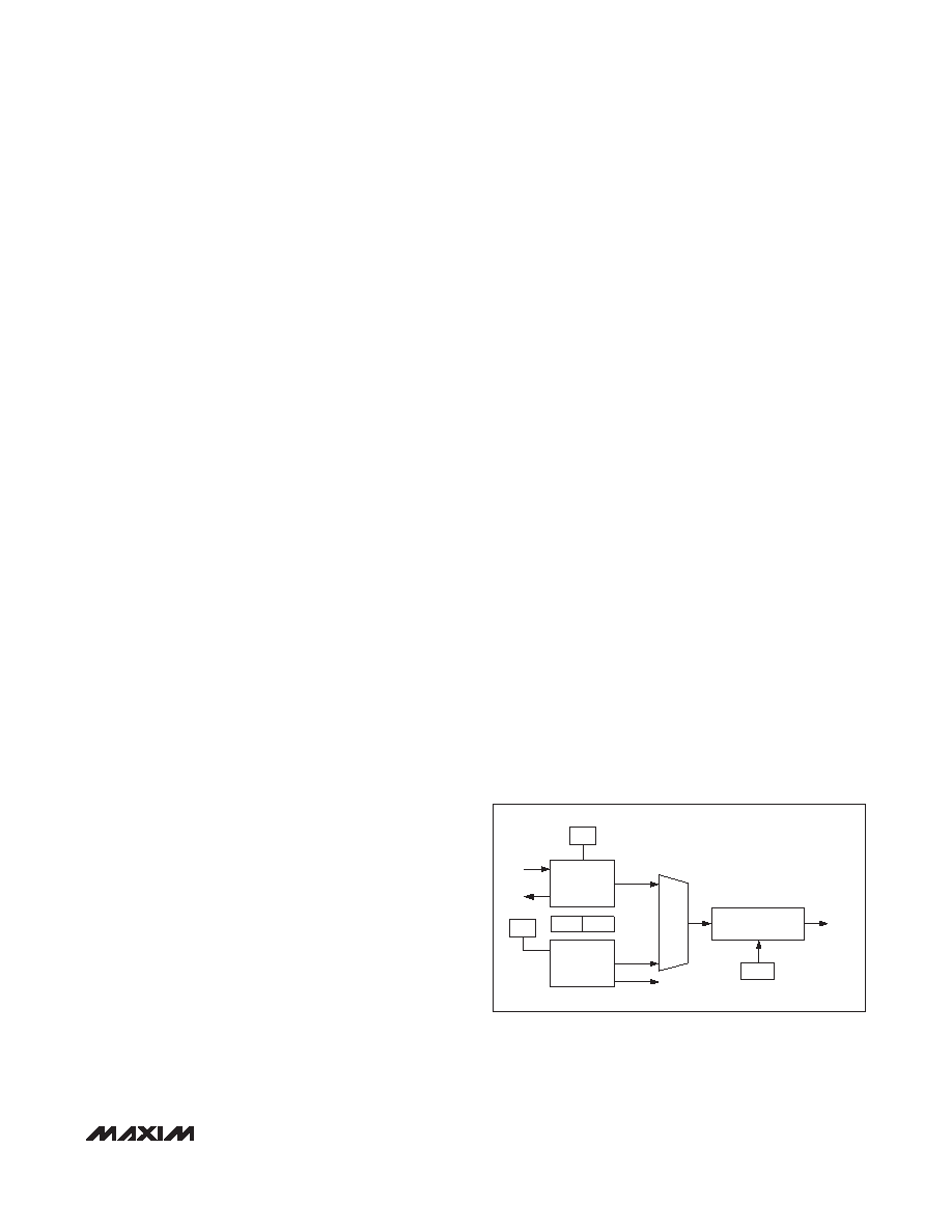
System Clock Generator
The MAXQ7666 oscillator module is the master clock
generator that supplies the system clock for the C
core and all of the peripheral modules using either a
crystal oscillator or an internal RC oscillator. The crystal
oscillator operates with an 8MHz crystal. Use the RC
oscillator in applications that do not require precise tim-
ing. The MAXQ7666 executes most instructions in a
single SYSCLK period. The oscillator module contains
all of the primary clock-generation circuitry. Figure 6
shows a block diagram of the system clock module.
The MAXQ7666 supports many features for generating
a master clock signal timing source:
Internal, fast-starting, 7.6MHz RC oscillator elimi-
nates external crystal
Internal high-frequency oscillator that can drive an
external 8MHz crystal
External high-frequency clock input (8MHz)
Selectable internal capacitors for high-frequency
crystal oscillator
Power-up timer
Fail-safe modes
Watchdog Timer
The primary function of the watchdog timer is to watch
for stalled or stuck software. The watchdog timer per-
forms a controlled system restart when the P fails to
write to the watchdog timer register before a selectable
timeout interval expires. In some designs, the watchdog
timer is also used to implement a real-time operating
system (RTOS) in the C. When used to implement an
RTOS, a watchdog timer typically has four objectives:
1) To detect if a system is operating normally
2) To detect an infinite loop in any of the tasks
3) To detect an arbitration deadlock involving two or
more tasks
4) To detect if some lower priority tasks are not running
because of higher priority tasks
CD0
SYSCLK
MUX
HFRCCLK
CLOCK
DIVIDE
HF
XTAL
OSC
RC
OSC
XIN
XOUT
XT
EXTHF
RCE
HFE
Figure 6. Crystal and RC Oscillator Block Diagram
相关PDF资料 |
PDF描述 |
|---|---|
| MB-91110PMT2 | 32-BIT, MROM, 50 MHz, RISC MICROCONTROLLER, PQFP144 |
| MB86602CPF | SCSI BUS CONTROLLER, PQFP100 |
| MB86604LPFV | SCSI BUS CONTROLLER, PQFP100 |
| MB86605PMT | SCSI BUS CONTROLLER, PQFP144 |
| MB86606PMT | SCSI BUS CONTROLLER, PQFP144 |
相关代理商/技术参数 |
参数描述 |
|---|---|
| MAXQ7666BATM+ | 功能描述:16位微控制器 - MCU RoHS:否 制造商:Texas Instruments 核心:RISC 处理器系列:MSP430FR572x 数据总线宽度:16 bit 最大时钟频率:24 MHz 程序存储器大小:8 KB 数据 RAM 大小:1 KB 片上 ADC:Yes 工作电源电压:2 V to 3.6 V 工作温度范围:- 40 C to + 85 C 封装 / 箱体:VQFN-40 安装风格:SMD/SMT |
| MAXQ7666BATM+T | 功能描述:16位微控制器 - MCU RoHS:否 制造商:Texas Instruments 核心:RISC 处理器系列:MSP430FR572x 数据总线宽度:16 bit 最大时钟频率:24 MHz 程序存储器大小:8 KB 数据 RAM 大小:1 KB 片上 ADC:Yes 工作电源电压:2 V to 3.6 V 工作温度范围:- 40 C to + 85 C 封装 / 箱体:VQFN-40 安装风格:SMD/SMT |
| MAXQ7667 | 制造商:MAXIM 制造商全称:Maxim Integrated Products 功能描述:16-Bit, RISC, Microcontroller-Based, Ultrasonic Distance-Measuring System |
| MAXQ7667AACM/V+ | 功能描述:16位微控制器 - MCU 16-Bit RISC MCU-Bsd Ultrasonic DMS RoHS:否 制造商:Texas Instruments 核心:RISC 处理器系列:MSP430FR572x 数据总线宽度:16 bit 最大时钟频率:24 MHz 程序存储器大小:8 KB 数据 RAM 大小:1 KB 片上 ADC:Yes 工作电源电压:2 V to 3.6 V 工作温度范围:- 40 C to + 85 C 封装 / 箱体:VQFN-40 安装风格:SMD/SMT |
| MAXQ7667AACM/V+T | 功能描述:16位微控制器 - MCU 16-Bit RISC MCU-Bsd Ultrasonic DMS RoHS:否 制造商:Texas Instruments 核心:RISC 处理器系列:MSP430FR572x 数据总线宽度:16 bit 最大时钟频率:24 MHz 程序存储器大小:8 KB 数据 RAM 大小:1 KB 片上 ADC:Yes 工作电源电压:2 V to 3.6 V 工作温度范围:- 40 C to + 85 C 封装 / 箱体:VQFN-40 安装风格:SMD/SMT |
发布紧急采购,3分钟左右您将得到回复。