- 您现在的位置:买卖IC网 > PDF目录80409 > MB90F803SPF-G (FUJITSU LTD) 16-BIT, FLASH, 25 MHz, MICROCONTROLLER, PQFP100 PDF资料下载
参数资料
| 型号: | MB90F803SPF-G |
| 厂商: | FUJITSU LTD |
| 元件分类: | 微控制器/微处理器 |
| 英文描述: | 16-BIT, FLASH, 25 MHz, MICROCONTROLLER, PQFP100 |
| 封装: | 20 X 14 MM, 3.35 MM HEIGHT, 0.65 MM PITCH, PLASTIC, QFP-100 |
| 文件页数: | 77/92页 |
| 文件大小: | 2178K |
| 代理商: | MB90F803SPF-G |
第1页第2页第3页第4页第5页第6页第7页第8页第9页第10页第11页第12页第13页第14页第15页第16页第17页第18页第19页第20页第21页第22页第23页第24页第25页第26页第27页第28页第29页第30页第31页第32页第33页第34页第35页第36页第37页第38页第39页第40页第41页第42页第43页第44页第45页第46页第47页第48页第49页第50页第51页第52页第53页第54页第55页第56页第57页第58页第59页第60页第61页第62页第63页第64页第65页第66页第67页第68页第69页第70页第71页第72页第73页第74页第75页第76页当前第77页第78页第79页第80页第81页第82页第83页第84页第85页第86页第87页第88页第89页第90页第91页第92页
MB90800 Series
DS07-13733-6E
79
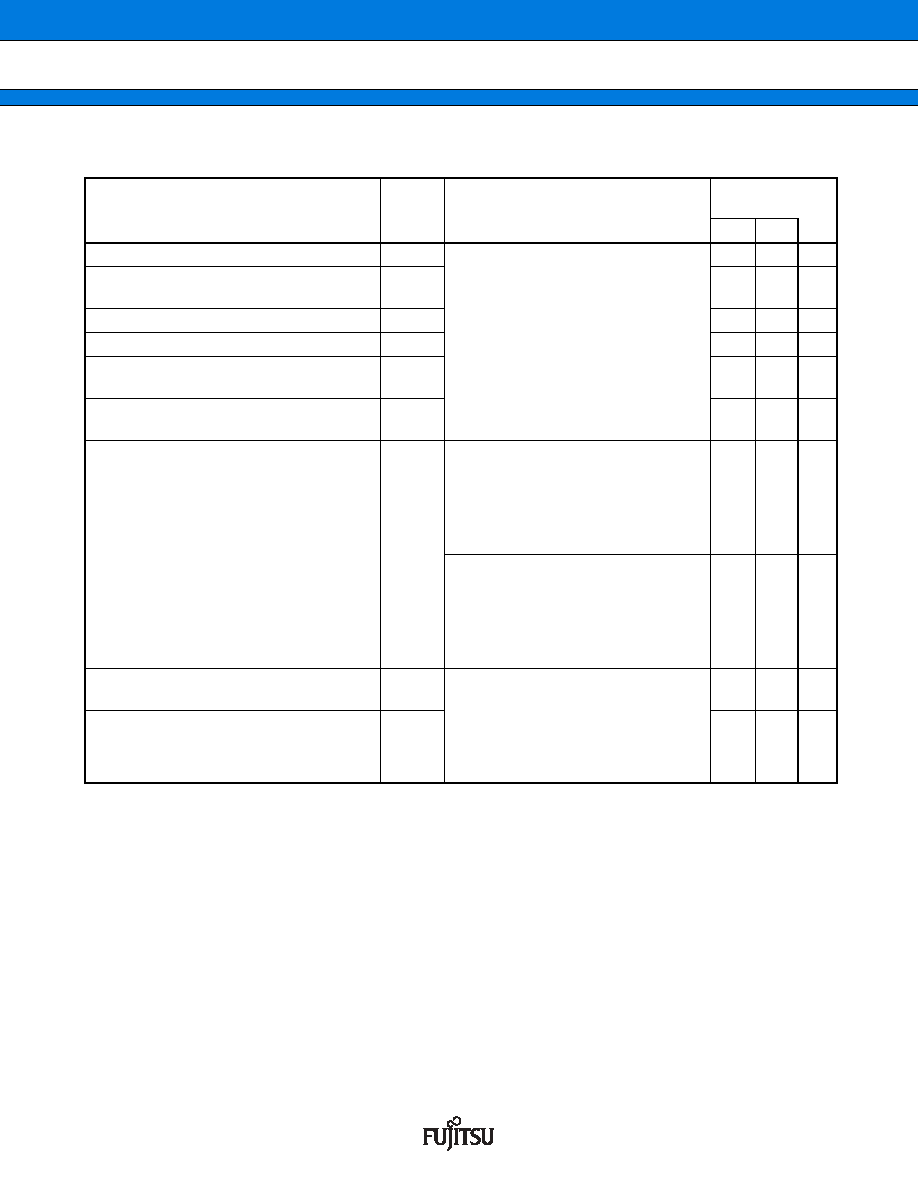
(8) I2C timing
(AVCC
= VCC = 3.3 V ± 0.3 V, VSS = AVSS = 0.0 V, TA = 40 °C to + 85 °C)
*1 : fCP is internal operation clock frequency. Refer to “ (1) Clock timing”.
*2 : R, C : Pull-up resistor and load capacitor of the SCL and SDA lines.
*3 : The maximum tHDDAT only has to be met if the device does not stretch the “L” width (tLOW) of the SCL signal.
*4 : Refer to “
Note of SDA and SCL set-up time”.
Parameter
Symbol
Conditions
Standard-
mode
Unit
Min
Max
SCL clock frequency
fSCL
When power supply voltage of external
pull-up resistor is 5.0 V
R
= 1.0 kΩ, C = 50 pF*2
When power supply voltage of external
pull-up resistor is 3.6 V
R
= 1.0 kΩ, C = 50 pF*2
0100
kHz
Hold time (repeated) START condition
SDA
↓ → SCL ↓
tHDSTA
4.0
μs
“L” width of the SCL clock
tLOW
4.7
μs
“H” width of the SCL clock
tHIGH
4.0
μs
Set-up time for a repeated START condition
SCL
↑ → SDA ↓
tSUSTA
4.7
μs
Data hold time
SCL
↓ → SDA ↓ ↑
tHDDAT
0
3.45
*3
μs
Data set-up time
SDA
↓ ↑ → SCL ↑
tSUDAT
When power supply voltage of external
pull-up resistor is 5.0 V
fCP*1
≤ 20 MHz, R = 1.0 kΩ, C = 50 pF*2
When power supply voltage of external
pull-up resistor is 3.6 V
fCP*1
≤ 20 MHz, R = 1.0 kΩ, C = 50 pF*2
250
*4
ns
When power supply voltage of external
pull-up resistor is 5.0 V
fCP*1
> 20 MHz, R = 1.0 kΩ, C = 50 pF*2
When power supply voltage of external
pull-up resistor is 3.6 V
fCP*1
> 20 MHz, R = 1.0 kΩ, C = 50 pF*2
200
*4
ns
Set-up time for STOP condition
SCL
↑ → SDA ↑
tSUSTO
When power supply voltage of external
pull-up resistor is 5.0 V
R
= 1.0 kΩ, C = 50 pF*2
When power supply voltage of external
pull-up resistor is 3.6 V
R
= 1.0 kΩ, C = 50 pF*2
4.0
μs
Bus free time between a STOP and START
condition
tBUS
4.7
μs
相关PDF资料 |
PDF描述 |
|---|---|
| MPC8543EVTANGA | 32-BIT, 800 MHz, MICROPROCESSOR, PBGA783 |
| MPC8545VUATG | 32-BIT, 1200 MHz, MICROPROCESSOR, CBGA783 |
| MPC8548HXAQGA | 32-BIT, 1000 MHz, MICROPROCESSOR, CBGA783 |
| MC312XDP512F0VFVR | 16-BIT, FLASH, 40 MHz, MICROCONTROLLER, PQFP144 |
| MSC8122TMP6400 | 32-BIT, 400 MHz, OTHER DSP, PBGA431 |
相关代理商/技术参数 |
参数描述 |
|---|---|
| MB90F804-201PFR-GE1 | 制造商:FUJITSU 功能描述: |
| MB90F867APFR-G-SNE1 | 制造商:FUJITSU 功能描述: |
| MB90F867ASPF-GE1 | 制造商:FUJITSU 功能描述:IC 16BIT MCU I2C SMD QFP100 |
| MB90F867ASPFR-GE1 | 制造商:FUJITSU 功能描述: |
| MB90F867ASPFR-G-SPE1 | 制造商:FUJITSU 功能描述: |
发布紧急采购,3分钟左右您将得到回复。